Pipe Flow Expert Software Calculations & Design Details
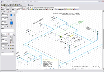
 The Pipe Flow Expert software will allow you to easily draw and model a piping design.
The pipe system is defined using Pipe Flow Expert's incredibly intuitive user interface, which also supports isometric 3D piping layouts.
Our focus on producing reliable, simple-to-use and yet powerful piping design software makes it easy for the pipe designer, saving countless hours, days, weeks and even months of effort.
Piping Design and Pipeline Modeling
 The piping model will typically include standard physical data such as:
- The internal size, internal roughness and length of each pipe.
- The elevation of each node (join point) where several pipes connect.
- The additional in-flow or out-flow (take off) at any particular node.
- The elevation, liquid level and surface pressure data for each tank.
- The flow versus head performance data for each pump.
The calculated results include the flow rates for each pipe, the fluid velocities for each pipe, Reynolds numbers, friction factors, friction pressure losses for each pipe, fittings losses, component pressures losses, node pressures, pipeline HGL (Hydraulic Grade Line), pump operating points (including pump head required) and more.
Flow Rate and Pressure Drop Calculations
Pipe Flow Expert calculates the balanced steady state flow rates, pipe pressure drops and node pressures within a piping system.
The Colebrook-White friction factor equation is used to determine the correct pipe friction factors and the Darcy-Weisbach friction loss calculation method is used to calculate the pipe friction losses.
Solving the Piping Design
To solve and calculate the flow and pressure loss results the following conditions have to be satisfied:
- Conservation of Mass Flow must be maintained, i.e. there must be mass flow continuity at every node (point where multiple pipes join) within the pipe system.
- Conservation of Energy must be maintained, i.e. the algebraic sum of the pressure losses around a loop in the pipe network must be zero.
The second condition can also be related to 'pseudo-loops' (any path between two tanks or end points in the system) such that the algebraic sum of the pressure losses in the pipes along the path must equal the difference in pressure between the start and end point.
Method of Solution
Pipe Flow Expert generates the fundamental conservation of energy and conservation of mass flow equations from the piping system model. It then uses advanced mathematical matrix methods to solve the resulting hydraulic equations, taking account of pumps, components, flow controls, PRVs, BPVs, pipe fittings, pipe materials, pipe sizes, and fluid data.
 The final solution is then checked by a second algorithm which compares the calculated pressure at all adjacent nodes to ensure that the pressure difference is equal to the pressure loss resulting from the flow in the pipe joining the nodes. This double check of the pipe network verifies that the calculated pressure at each node is consistent, irrespective of which path through the network is used to calculate the pressure loss back to a particular pressure reference.
Finding an accurate solution of the flows and pressures in a pipe network is not an easy task. It is many orders of magnitude more difficult than finding the pressure loss in a single pipe for a known flow rate, which is why it is important to use proven software with a reliable calculation engine. Pipe Flow Expert is trusted by users in over 100 countries worldwide.
Next: Pipe Flow Expert Software Brochure


