Pipe Pressure Drop Calculations
 When fluid flows through a pipe there will be a pressure drop that occurs as a result of resistance to flow. There may also be a pressure gain/loss due a change in elevation between the start and end of the pipe. This overall pressure difference across the pipe is related to a number of factors:
- Friction between the fluid and the wall of the pipe
- Friction between adjacent layers of the fluid itself
- Friction loss as the fluid passes through any pipe fittings, bends, valves, or components
- Pressure loss due to a change in elevation of the fluid (if the pipe is not horizontal)
- Pressure gain due to any fluid head that is added by a pump
Calculating the Pressure Drop in a Pipe
To calculate the pressure loss in a pipe it is necessary to compute a pressure drop, usually in fluid head, for each of the items that cause a change in pressure. However to calculate the friction loss in a pipe for example, it is necessary to calculate the friction factor to use in the Darcy-Weisbach equation which determines the overall friction loss.
 The friction factor itself is dependent on internal pipe diameter, the internal pipe roughness and the Reynold's number which is in turn calculated from the fluid viscosity, fluid density, fluid velocity and the internal pipe diameter.
There are therefore a number of sub-calculations that must take place to calculate the overall friction loss. Working backwards we must know the fluid density and viscosity properties, know the pipe diameter and roughness properties, calculate the Reynold's number, use this to calculate the friction factor using the Colebrook-White equation, and finally plug in the friction factor to the Darcy-Weisbach equation to calculate the friction loss in the pipe.
After calculating the pipe friction loss we then need to consider possible fitting losses, change in elevation and any pump head added. Summing these losses/gains will give us the overall pressure drop in the pipe. The following sections consider each calculation in turn.
Pipe Friction Loss Calculations
We now need to calculate each of the items that is required to determine the friction loss in the pipe. The links in the following list provide more details about each specific calculation:

- Fluid Density
- Fluid Viscosity
- Pipe Roughness Measurement
- Reynold's Number - Laminar Flow or Turbulent Flow
- Friction Factors - Moody Chart and Colebrook-White Equation
- Friction Loss in a pipe - Darcy-Weisbach Method
Our Pipe Flow software automatically calculates the friction loss in pipes using the Darcy-Weisbach equation since this is the most accurate method of calculation for non-compressible fluids, and it is also accepted as industry accurate for compressible flow provided certain conditions are met.
Pipe Fitting Loss Calculations
Energy loss due to valves, fittings and bends is caused by some localized disruption of the flow. The dissapation of the lost energy occurs over a finite but not necessarily short section of the pipeline, however for hydraulic calculations it is accepted practice to consider the entire amount of this loss at the location of the device.
For pipe systems with relatively long pipes, it is often the case that fitting losses will be minor in relation to the the overall pressure loss in the pipe. However some local losses such as those produced by a part open valve are often very signifcant and can never be termed a minor loss, and these must always be included.
The loss that a specific pipe fitting introduces is measured using real world experimental data and this is then analyzed to determine a K factor (a local loss coefficient) that can be used to calculate the fitting loss as it varies with the velocity of the fluid passing through it.
Our Pipe Flow Software programs make it easy to automatically include fitting losses and other local losses in the pressure drop calculation since they come with a pre-loaded fittings database that contains many industry standard K factors for various different valves and fittings, at various different sizes.
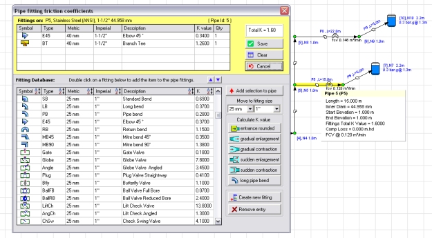
All the user has to do is to select the appropriate fitting or valve, and then choose 'Save' to add this on to the pipe, and have it included in the pipe pressure loss calculation.
This link provides more information on Fitting K Factors and the Fittings Loss Equation.
Pipe Component Loss Calculations
There are often many different types of components that need to be modeled in a piping system, such as a heat exchanger or a chiller. Some components may introduce a known fixed pressure loss however it is more likely that the pressure drop will vary with the flow rate passing through the component.
Most manufacturers will supply a component performance curve that describes the flow verus head loss characteristics of their product. This data is then used to calculate the pressure loss caused by the component for a specified flow rate but the flow rate itself will also be dependent on the pressure loss downstream of the component and so it is very difficult to model component head loss performance without the use of appropriate software such as Pipe Flow Expert.
Pressure Loss due to Change in Elevation
Flow in a rising pipe
If the start elevation of a pipe is lower than the end elevation then on top of friction and other losses there will be an additional pressure loss caused by the rise in elevation, which measured in fluid head is simply equivalent to the rise in elevation.
i.e. at a higher fluid elevation there is less pressure added due to the reduced depth and weight of fluid above that point.
Flow in a falling pipe
If the start elevation of a pipe is higher than the end elevation then as well as the friction and other losses there will be an additional pressure gain caused by the drop in elevation, which measured in fluid head is simply equivalent to the fall in elevation.
i.e. at a lower fluid elevation there is more pressure added due to the increased depth and weight of fluid above that point.
Energy and Hydraulic Gradelines
The elevation of a fluid within a pipe, together with the pressure in the pipe at a specific point, and the velocity head of the fluid, can be summed to calculate what is known as the Energy Grade Line.
The Hydraulic Grade Line can be calculated by subtracting the fluid's velocity head from the EGL (Energy Grade Line), or simply by summing only the fluid elevation and the pressure in the pipe at that point.
Pump Head Calculations
Within a pipe system there is often a pump which adds additional pressure (known as 'pump head') to overcome friction losses and other resistances. The performance of a pump is usually available from the manufacturer, in terms of the pump performance curve, which plots a graph of the flow versus head produced by the pump for a range of flow values.

Since the head produced by the pump varies with the flow rate, finding the operating point on the pump performance curve is not always an easy task. If you guess a flow rate and then calculate the pump head added, this in turn will affect the pressure difference in the pipe, which itself actually affects the flow rate that would occur.
Of course if you use our Pipe Flow Expert Software then it will find the exact operating point on the pump curve for you, ensuring that the flows and pressures balance throughout your system to give an accurate solution your piping design.
However you calculate the pump head added in your pipe, this additional fluid head must be added back to any pressure drop that has occured in the pipe.
Overall Pipe Pressure Drop Calculation
The pressure at the end of the pipe under consideration is therefore given by the following equation (where all items are specified in m Head of Fluid):
P[end] = P[start] - Friction Loss - Fittings Loss - Component Loss + Elevation[start-end] + Pump Head
where
P[end] = Pressure at end of pipe
P[start] = Pressure at start of pipe
Elevation[start-end] = (Elevation at start of pipe) - (Elevation at end of pipe)
Pump Head = 0 if no pump present
The pressure drop or rather pressure difference dP (it could be a gain) between the start and the end of a pipe is therefore given by this equation:
dP = Friction Loss + Fittings Loss + Component Loss - Elevation[start-end] - Pump Head
where
P[end] = Pressure at end of pipe
P[start] = Pressure at start of pipe
Elevation[start-end] = (Elevation at start of pipe) - (Elevation at end of pipe)
Pump Head = 0 if no pump present
Note dP is normally specified as a positive value relating to the drop in pressure. A negative value would indicate a pressure gain.