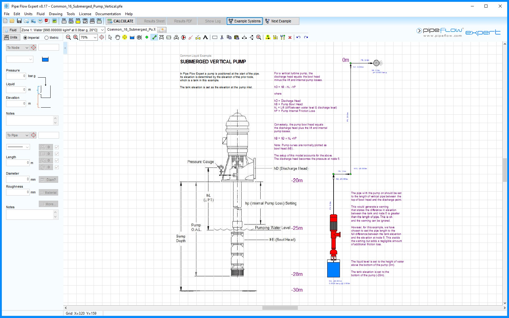
Common 16 – Vertical Submerged Pump

Figure 16 Common 16 – Vertical Submerged Pump
In Pipe Flow Expert a pump is positioned at the start of the pipe. Its elevation is determined by the elevation of the prior node, which is a tank in this example. The tank elevation is set as the elevation at the pump inlet. For a vertical turbine pump, the discharge head (hD) equals the bowl head (hB) minus the lift (hL) and internal pump losses (hP).
hD = hB - hL - hP where
hD = Discharge Head
hB = Pump Bowl Head
hL = Lift (diff between water level & discharge level)
hP = Pump Internal Friction Loss
Conversely, the pump bowl head equals the discharge head plus the lift and internal pump losses.
hB = hD + hL +hP
Note: Vertical turbine pump curves are normally plotted as bowl head (hB).
The setup of this model accounts for the above. The discharge head becomes the pressure at node 6.
The pipe with the pump on should be set to the length of vertical pipe between the top of bowl head and the discharge point. This would generate a warning that states the difference in elevation between the tank and node 6 is greater than the length of pipe. This is ok and the warning can be ignored. However, for this example, we have chosen to set the pipe length to the full difference between the tank elevation and the elevation at node 6. This avoids the warning but adds a negligible amount of additional friction loss.

