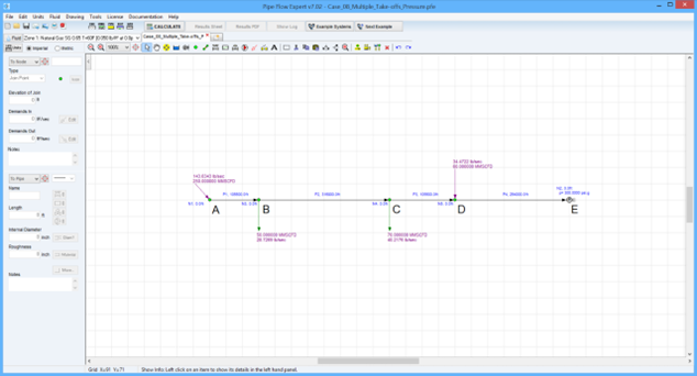
Case 08: Natural Gas Pipeline Outlet Pressures with Multiple Take-Offs
Reference: Gas Pipeline Hydraulics, 2005, CRC Press, E. Shashi Menon Chapter 3, page 94 Example 2a
Pipe Flow Expert File: Case_08_Multiple_Take-offs_Pressure.pfe
Problem Description:
A 150 mile pipeline carrying methane consists of several injections and deliveries.
The pipe internal diameter is 19 inches and at point A has an inlet volume of 250 MMSCFD.
At point B (20 miles downstream of the inlet) 50 MMSCFD is delivered and at point C (80 miles downstream of the inlet) 70 MMSCFD is delivered.
At point D, 100 miles downstream of the inlet, gas enters the pipeline at 60 MMSCFD.
Point E represents the end of the pipeline, 150 miles downstream of the inlet.
Calculate the pressures at points A, B, C and D for a minimum delivery pressure of 300 psi.g at point E.
Use a drag factor of 0.96 and a compressibility factor of 0.85 throughout.
The calculation method used for the published data was the American Gas Association (AGA) equation.

Pipe Flow Expert Parameters:
Fluid Data: Gas with gravity 0.65 (0.04964 lb/ft3), 60 °F at 0.00 psi.g, viscosity 0.0119 centipoise.
Pipe Data: Roughness 150 micro-inches.
Calculation Method: AGA Isothermal Flow equation with 0.96 drag factor, Node Adjust Method.
Standard Atmospheric Model: 60°F, 14.696 psi.
Gas Physical Model: Real Gas Model (Ideal Gas Law with custom compressibility factor Z=0.85).
Result Comparison:
|
Data Item |
Published data |
Pipe Flow Expert |
|
Inlet pressure A (psi.g) |
927.34 |
924.18 |
|
Outlet pressure B (psi.g) |
832.25 |
832.58 |
|
Outlet pressure C (psi.g) |
610.36 |
612.59 |
|
Outlet pressure D (psi.g) |
572.41 |
572.52 |
Commentary:
The published data and the calculated results compare well.
The calculations used for the published results used an approximation by re-using the AGA transmission factor from the first pipe section (D – E) for all of the other pipe sections, whereas Pipe Flow Expert calculated the AGA transmission factor separately for each pipe section (which is more accurate).

