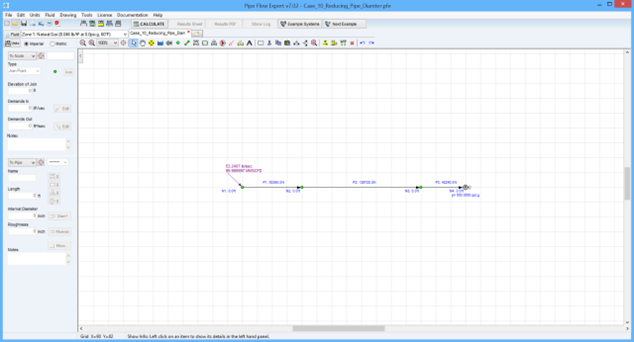
Case 10: Inlet Pressure of Natural Gas Pipeline with Reducing Pipe Diameter
Reference: Gas Pipeline Hydraulics, 2005, CRC Press, E. Shashi Menon Chapter 3, page 107 Example 5
Pipe Flow Expert File: Case_10_Reducing_Pipe_Diameter.pfe
Problem Description:
A series piping system consists of 12 miles of pipe, internal diameter 15.25 inches, connected to a length of pipe 24 miles long with internal diameter 13.5 inches, which in turn is connected to an 8 mile section of pipe of internal diameter 12.25 inches.
Use a compressibility factor of 0.9.
The gas flow rate is 100 MMSCFD and the delivery pressure is 500 psi.g.
Calculate the inlet pressure.
The calculation method used for the published data was the General Flow equation.

Pipe Flow Expert Parameters:
Fluid Data: Gas with specific gravity 0.6 (0.046 lb/ft3), 60 °F, 0.00 psi.g, viscosity 0.0119 centipoise.
Pipe Data: Roughness 0.0145 inches, all pipes.
Calculation Method: General Isothermal Flow equation, Node Adjust Method.
Standard Atmospheric Model: 60°F, 14.696 psi.
Gas Physical Model: Real Gas Model (Ideal Gas Law with compressibility factor Z=0.9)
Result Comparison:
|
Data Item |
Published data |
Pipe Flow Expert |
|
Inlet pressure (psi.g) |
980.1 |
982.7 |
Commentary:
The published data and the calculated results compare well.
The published literature states that a friction factor of 0.02 was used for all pipes, whereas Pipe Flow Expert calculates the friction factor for each pipe separately. In order to achieve an average friction factor of approximately 0.02 for the system, a large pipe roughness of 0.0145 inches was used.

