Add a Tank
To add a tank to the pipe system:
- Click the Add Tank button,
 , on the tool bar.
- When you click the Add Tank button, the tank symbol is displayed next to your mouse pointer when the pointer is in the Drawing pane.
- Click on the place on the Drawing pane where you want to add a tank.
- The tank is added to the system, and is selected on the Drawing pane. Define the tank’s properties in the Node pane.
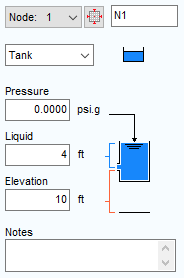
- Type the tank’s name in the Node field.
- Tank is automatically selected in the Type list.
- Click the Tank Icon button to select the tank image you want displayed on the pipe system drawing. The icon size can be selected from a range of scales. The image you select does not affect any of the tank’s properties or values.
- Type the surface pressure of the fluid in the tank in the Surface Pressure field.
- Type the amount of fluid above the tank exit point in the Liquid Level field.
- Type the exit elevation from the tank in the Elevation (Exit) field.
- Type any applicable notes regarding the tank in the Notes field.
- To add additional tanks to the system, repeat Steps 3 – 12.