Adding a Component with a pressure loss
To add a component’s pressure loss to a pipe:
- You can add the pressure loss using the Add Component Pressure Loss button on the toolbar or the Add/Change Component Pressure Loss button in the Pipe Pane.
- To add a pressure loss using the Add Component Pressure Loss tool bar button, click the Add Component Pressure Loss button,
 .
.
- When you click the Add Component Pressure Loss button, the pressure loss symbol is displayed next to your mouse pointer when the pointer is in the Drawing pane.
- Click on the pipe on the Drawing pane where you want to add a component pressure loss.
- Clicking on the pipe opens the Component Pressure Loss dialog.
- To add a pressure loss using the Add/Change Component Pressure Loss button in the Pipe pane, first select the pipe to which you want to add a Component in the Drawing pane, so that the pipe’s information is displayed in the Pipe pane.
- Click the Add/Change Component Pressure Loss button,
 in the Pipe pane.
- The number of component pressure losses currently on the selected pipe is displayed on the Add/Change Component Pressure Loss button. Clicking the Add/Change Component Pressure Loss button opens the Set Component Pressure Loss dialog.
- To add a component’s pressure loss data from an existing .pfco file, click the Load From File button, select the applicable .pfco file, click Open, edit the applicable fields, and then click the OK button. An image of the component pressure loss screen is shown below this step.
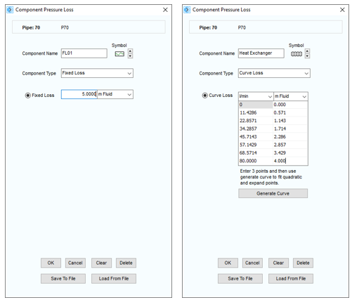
Figure 64 Set Component Pressure Loss
- Select the Fixed Loss Component Type, if the component’s pressure loss is a fixed pressure loss, and type the fixed pressure loss value.
- Select the Curve Loss Component Type, if the component’s pressure loss is based on a data curve.
- Select Cv or Kv Component Type if the component flow versus pressure loss is defined in this manner, and type the appropriate value. See the next section about Cv and Kv values for specific information about entering and using this type of data.
- Select the Sprinkler K (imperial) or Sprinkler K (metric) Component Type if the component flow versus pressure loss is defined by this type of value. A sprinkler will often have a specific Sprinkler K value (this is different to a normal K value for head loss through a fitting, and it is different to a Kv value that is normally associated with a valve). See the later section on Sprinkler K values.
- Select the Orifice Component Type if the component pressure loss occurs due to a sharp-edged, round-edged, bevel-edged, or thick-edged orifice. See the later section on defining Orifice data.
- A symbol appropriate for the chosen Component Type is selected by default. The symbol can be changed by clicking the Symbol Scroll Up or Scroll Down button to select the component pressure loss image you want to be displayed on the pipe system drawing.
- The image you select does not affect any of the component’s pressure loss properties or values.
- Select the applicable units for the component pressure loss curve from the Curve Loss flow and head lists.
- The left Curve Loss column represents the fluid’s flow values, and the right Curve Loss column represents the fluid head loss or pressure loss values.
- Determine which points in the component’s pressure loss curve data (as provided by the component manufacturer) that you want to include in the component pressure loss curve, and then type the flow and head loss values for each of these points in the Curve Loss table.
- Add a minimum of three and maximum of eight points in the Curve Loss table. After adding three curve points to the table, you can have Pipe Flow Expert calculate a ‘curve’ through these points, to expand the number of data points automatically (fitting points on this curve). Click the Generate Curve button to perform this action.
- Click OK to save and add the component pressure loss data to the pipe.
The pressure loss data you enter can be saved to a .pfco file by clicking the Save To File button. By saving the data to a .pfco file, you can reuse the component’s pressure loss data for other pipes in the pipe system or future pipe systems.
When a component pressure loss is added to a pipe, the Include check box is displayed and selected next to the Add/Change Component Pressure Loss button,  . When the Include check box is selected, Pipe Flow Expert includes the data from the component pressure loss on the pipe in the calculations for solving the pipe system. To remove the component pressure loss data from the calculations, clear the Include check box.
Information about calculating and solving pipe systems is available in the Section: Calculating the System Flow and Pressure.