Adding a Pipe
To add a pipe to the pipe system:
- Click the Add Pipes button,
 , on the tool bar.
- When you click the Add Pipes button, the pipe symbol is displayed next to your mouse pointer when the pointer is in the Drawing pane.
- Click on the place on the Drawing pane where you want the pipe to start.
- Click on the place where you want the pipe to end.
- The pipe is added to the system, and is selected in the Drawing pane. Define the pipe’s properties in the Pipe Pane.
- The rubber-banding functionality of the Add Pipes feature provides the ability to continue drawing additional connected sections of pipe after adding a section of pipe.
- If you want to continue adding connected lengths of pipe to the system, move the mouse pointer to draw the pipe, and click where you want the pipes to end. To turn off the rubber-banding, press the right mouse button (right-click).
- Type the pipe’s name in the Name field.
- If the default pipe type and values for the system are defined on the Default Values tab in the Configuration Options dialog, you are done adding the pipe.
- The pipe type, default length, internal diameter and roughness values are displayed in the Pipe pane.
- If the default pipe values are not being used for the pipe, continue with Steps 12 to 25.
- Type the length of the pipe into the Length field.
- Click the Material button.
- Clicking the Material button opens the Pipe diameter database. A list of all the pipe materials available in the pipe database are displayed in the Choose new pipe material list.
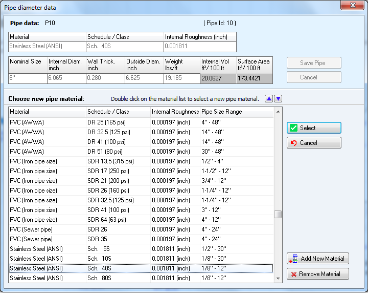
Figure 53 Pipe diameter data - materials list
- Select the pipe’s material from the Choose new pipe material list.
- If the pipe material is not in the Choose new pipe material list, click the Add new material button to add the new material to the list. For more information about adding a pipe material, see: Adding a Pipe Material to the Database
- Click the Select button or double-click the row containing the material.
- The selected material is displayed in the Pipe data section of the Pipe diameter data dialog, and a list of all the different pipe sizes available for the selected pipe material is displayed in the Pipe diameter data dialog.
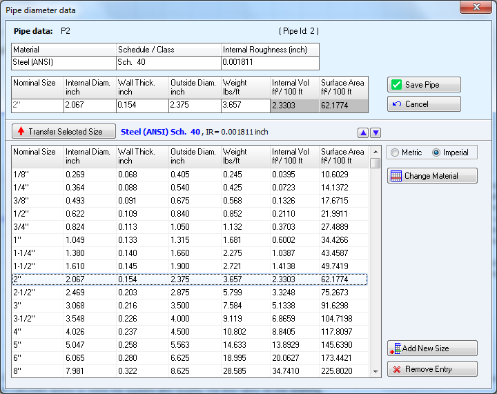
Figure 54 Pipe diameter data - pipe sizes
- Select the applicable pipe size from the list.
- If the pipe size is not in the list, click the Add new size button to add the new size to the list. For more information about adding a pipe size, see: Adding Pipe Size Data to the Database
- Click the Transfer Selected Size button or double-click the row containing the size.
- The selected size is displayed below the pipe material in the Pipe data section of the Pipe diameter data screen.
- Edit the applicable pipe properties in the Pipe data section.
- The edits made only affect the current pipe’s properties; they do not affect the database data.
- Click Save Pipe to add the pipe’s material and size, and to close the Pipe diameter data screen.
The pipe’s material is displayed under the Roughness field, the nominal size is displayed under the Diam button, and the pipe’s length, internal diameter, and roughness are displayed in the Length, Internal Diameter, and Roughness fields in the Pipe pane.