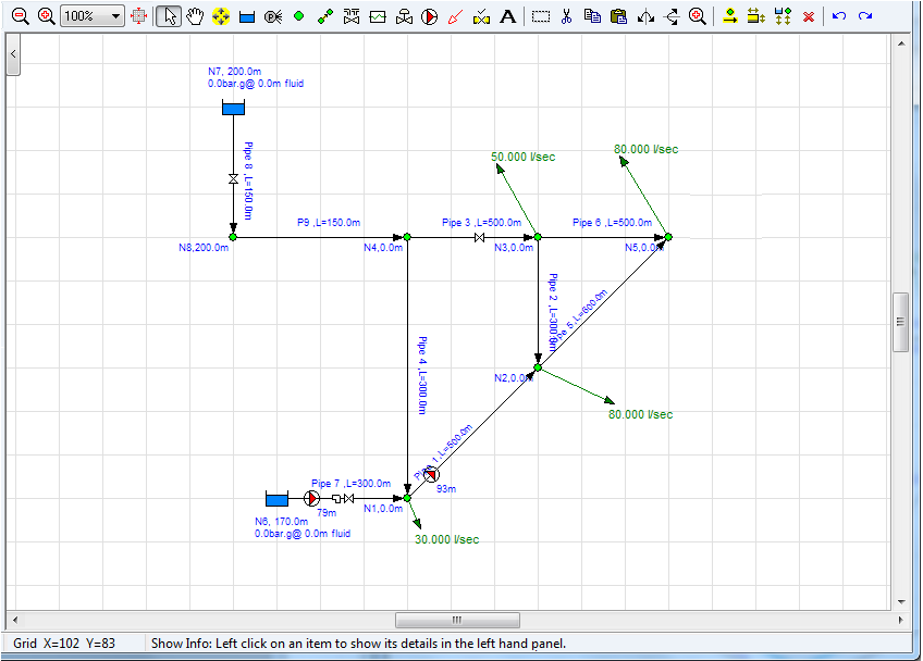
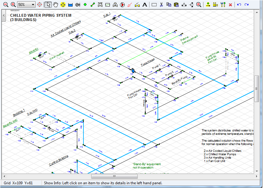
Drawing Pane


Figure 24 Drawing Panes Standard or Isometric
|
Feature |
Description |
|
Drawing Grid |
The drawing grid shows details of the pipeline system. The information to be displayed, such as size, length, elevation, flow rate etc. can be selected from the configuration options labelling tab. |
|
Hint Feature |
The Hint pane, located above the tool bar, displays tips for using the button currently selected on the tool bar. |
|
Zoom Feature |
If your mouse is suitable the drawing size can be zoomed larger or smaller using the mouse scroll wheel. |
|
Drawing Size Display |
The drawing size can be selected from the drop down listing between the Zoom Out and the Zoom In buttons. |
|
Zoom Out Button |
Click to make the drawing size smaller by one step. |
|
Zoom In Button |
Click to make the drawing size larger by one step. |
|
Zoom drawing to fit on screen |
Click to fit all of the drawing on the screen. |
Pipe Flow Expert offers a choice of a drawing grid with square increments for standard designs or an isometric grid for use where it is desirable to create an isometric view.
It is possible to toggle between standard / isometric design grids.
Moving from a standard grid to an isometric grid transposes the standard drawing on to a flat isometric plane. A user can then adjust/move the nodes as necessary to produce a drawing that looks 3D.
Moving from an isometric grid to a standard grid transposes the isometric drawing to a flattened view that produces a near plan view (except that PipeFlow Expert does not allow nodes to appear at the same point on the grid and therefore nodes directly above or below each other on the isometric grid are offset at a diagonal angle when transposed to the flat view).
The system design can be amended in either drawing mode.

