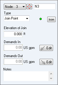
Join Point Data

Figure 15 Join Point Node Pane
|
Feature |
Description |
|
Node Identification Number |
Use the Node Drop Down List to select a node or to scroll through each of the nodes in the pipe system. |
|
Node |
The name of the node currently selected in the Drawing pane. Use the Node field to edit the node name. |
|
Type (Join Point) |
The type of node currently selected in the Drawing pane. Use the Type field to modify the node type. There are three types of nodes – join point, tank, or demand pressure (End Pressure). |
|
Type (Join Point) Icon |
The icon size can be selected from a range of scales. The image you select does not affect any of the joint point properties or values. |
|
Elevation of Join Point |
The elevation of the join point expressed in the units displayed. |
|
Demands In (at Join Point) |
View the In Flow to the system at this node. Click edit to change. |
|
Demands Out (at Join Point) |
View the Out Flow from the system at this node. Click edit to change. |
|
Edit buttons (Join Point) |
Opens the Set Flow Demands dialog. This dialog is used to set a demand flow on the join point. |
|
Notes |
Notes about the node currently selected in the Drawing pane. Notes can be up to 200 characters. |


