Loops, Nodes and Pipes
To solve the unknowns in any pipeline network, a system of nonlinear equations must be developed to mathematically describe the pipeline network in terms of the flows and pressures that must balance at specific points within the system. These equations must be solved simultaneously in order to find a balanced solution.
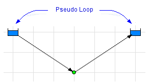
Loops within a pipeline network consist of a series of connected pipes that return to the start point (the node where the loop started), however pseudo loops can exist between a supply or discharge source, between two supply sources or between two discharge sources.

A series of pressure equations describing the pressure loss in each loop must be generated. The same pipe may be included in many different loops.
Where a loop includes a number of different fluid zones the elevation differences of the nodes and the density of the fluid in each pipe along the path in the loop must be used to establish the difference in pressures due to fluid density at the end points of the loop. This pressure difference is used together with the fluid surface pressure difference to establish the net pressure difference around the loop.
Pressure losses and pressure gains within each pipe must take account of changes in elevation, fittings, control valves (including FCVs, PRVs, & BPVs), components (including valves defined with Cv, Kv, & Sprinkler K values, and different types of Orifices), and pumps.
A series of mass flow continuity equations must be generated for the mass flow rate balance at each node in the pipeline system.
The Pipe Flow Expert software will automatically analyze a system, identify all loops and pseudo-loops, generate the pressure equations throughout the network and remove redundant loop equations (those which are already fully described by combining other equations). It will also generate the mass flow balance equations for each node in a pipeline system.

