Modeling a Spray Nozzle with a Sprinkler K Factor
Many systems include points where flow will discharge to atmosphere. When a spray nozzle is included in the design it is usual to use the flow versus pressure loss characteristic of the spray nozzle to establish the flow leaving the system due the pressure differential across the nozzle.
A combination of a Component and an End Pressure node can be used to model the performance of a spray nozzle.
The End Pressure node should be set to 0.000 psi.g, if the spray discharges to atmosphere. If the spay discharges to a pressurized tank then the End Pressure node should be set to the pressure in the tank.
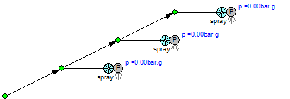
Figure 68 Modeling a Spray Nozzle
To add a component with a Sprinkler K value:
- Add a component to a pipe as described in the previous sections.
- Type the name of the control valve in the Component Name field.
- The symbol appropriate for the chosen Component Type is selected by default. The symbol can be changed by clicking the Symbol Scroll Up or Scroll Down button to select the component pressure loss image you want displayed on the pipe system drawing.
- Select the Sprinkler K radio button (for imperial or metric values) and enter the Sprinkler K factor value (or use the calculator helper to compute a sprinkler K factor for a given flow rate and pressure drop characteristic of the sprinkler).
- Click OK to save and add the Sprinkler K factor data to the pipe.
Note: The component dialog includes ‘helpers’ to assist in calculating an appropriate Sprinkler K value for a particular flow rate and pressure drop (based on the current fluid).