Orifices Loss Coefficient
Orifices are widely installed in piping systems and hydraulic machinery to produce a regular and reproducible loss of pressure. Orifices are used to limit flow, or, in branching systems, to balance distributed flow, or to measure flow.
There are several different approaches and equations that are used in literature to estimate the pressure loss through an orifice for a specified flow rate. In many cases the methods do not treat the pressure loss calculation consistently, and common physical properties of the orifice are not used in a standard manner. In some cases, the pressure drop estimate relies on a discharge coefficient, and in other cases it is simply presented as graph plot of pressure drop versus flow rate (or pressure drop derived as a percentage of differential pressure across flow measurement).
The Pipe Flow Expert software orifice calculations use a more generalized model, which utilizes the broad physical attributes of the orifice to determine the flow characteristics. This generates a K0 value (a k factor) that can be applied in a standard method as follows:

Where:
|
H0 = Head Loss (in ft or m of fluid, depending on the units of velocity, ft/s or m/s) |
|
K0 = K factor (for the density and velocity of fluid flow through the orifice diameter) |
|
g = acceleration due to gravity (in ft/s2 or m/s2) |
While this final equation provides a standard method for calculating the pressure drop through different types of orifice, deriving the K0 factor and then applying it to orifice calculations in a complex pipe network (particularly in compressible gas systems where the density and velocity at the orifice inlet varies with pressure changes in the system), is a complex task, which also then relies on the development of further algorithms that allow convergence to balanced solution across the whole model.
The Pipe Flow Expert software handles the complexity of the calculations and makes it easy to perform calculations with orifices in pipes systems. The following sections detail the equations used to derived the orifice K0 value.
Sharp-Edged Orifice in a Straight Pipe
A sharp-edged orifice in a straight pipe, where the upstream and downstream pipe sizes are the same, as illustrated in Figure 128.
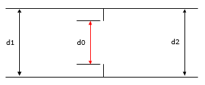
Figure 128 Sharp Edged Orifice in a Straight Pipe
The loss coefficient (K0) of a straight edged orifice in a straight pipe is calculated as follows:
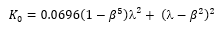
Where the diameter ratio β = d0/d1 and the jet velocity is given by:

Sharp-Edged Orifice in a Transition Section
A sharp-edged orifice in a transition section, where the upstream and downstream pipe sizes are not the same, are illustrated in Figure 129 and Figure 130.
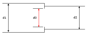
Figure 129 Sharp Edged Orifice in a Transition Section (Contraction)
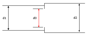
Figure 130 Sharp Edged Orifice in a Transition Section (Expansion)
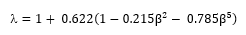
The loss coefficient (K0) of a sharp-edged orifice in a transition section is calculated as follows:
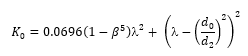
Where the diameter ratio β = d0/d1 and the jet velocity is given by:
Sharp-Edged Orifice Discharging to Atmosphere
A sharp-edged orifice that discharges to atmosphere is illustrated in Figure 131.
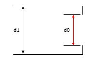
Figure 131 Sharp Edge Orifice Discharging to Atmosphere
For this orifice configuration, the loss coefficient (K0) equation for a sharp-edged orifice in an expanding transition section can be used, however the downstream pipe diameter (d2) is effectively infinite and therefore the equation can be transformed into:
Round Edged Orifice in a Straight Pipe
A round edged orifice in a straight pipe, where the upstream and downstream pipe sizes are the same, is illustrated in Figure 132.
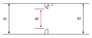
Figure 132 Round Edged Orifice in a Straight Pipe
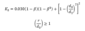
The loss coefficient (K0) of a round edged orifice in a straight pipe is calculated as follows:
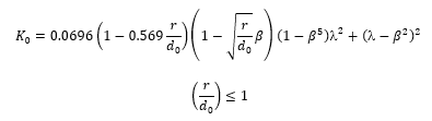
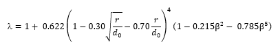
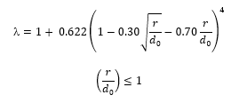
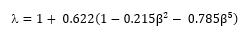
Where the diameter ratio β = d0/d1 and where the jet contraction coefficient is given by:
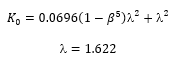
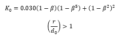
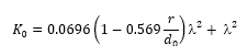
In the case of a generously rounded orifice where r/d0 is equal to or greater than 1, the jet contraction ratio equals 1 and the loss coefficient becomes:
Round Edged Orifice in a Transition Section
A round edged orifice in a transition section, where the upstream and downstream pipe sizes are not the same, are illustrated in Figure 133 and Figure 134.
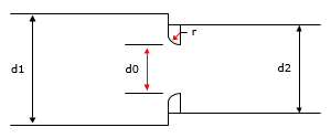
Figure 133 Round Edged Orifice in a Transition Section (Contraction)
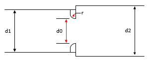
Figure 134 Round Edged Orifice in a Transition Section (Expansion)
The loss coefficient (K0) of a round edged orifice in a transition section is calculated as follows:
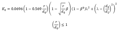
Where the diameter ratio β = d0/d1 and where the jet contraction coefficient is given by:
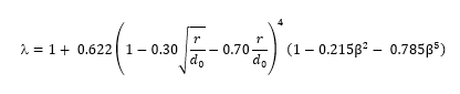
In the case of a generously rounded orifice where r/d0 is equal to or greater than 1, the jet contraction ratio equals 1 and the loss coefficient becomes:
Round Edged Orifice Discharging To Atmosphere
A round edged orifice that discharges to atmosphere is illustrated in Figure 135.
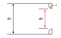
Figure 135 Round Edged Orifice Discharging to Atmosphere
For this orifice configuration, the loss coefficient (K0) equation for a round edged orifice in an expanding transition section can be used, however the downstream pipe diameter (d2) is effectively infinite and therefore the equation can be transformed into:
where the jet contraction coefficient is given by:
Bevel Edged Orifice in a Straight Pipe
A bevel edged orifice in a straight pipe, where the upstream and downstream pipe sizes are the same, is illustrated in Figure 136.
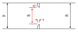
Figure 136 Bevel Edged Orifice in a Straight Pipe
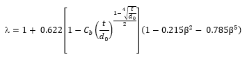
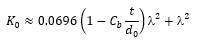
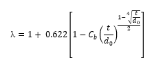
The loss coefficient (K0) of a bevel edged orifice in a straight pipe is calculated as follows:
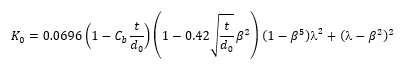
Where the diameter ratio β = d0/d1 and where the jet contraction coefficient is given by:
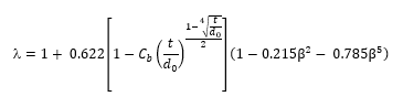
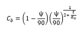
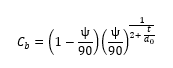
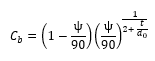
And where Cb is a function of bevel angle ψ in degrees, and bevel thickness to diameter ratio t/d0 is given by:
Bevel Edged Orifice in a Transition Section
A bevel edged orifice in a transition section, where the upstream and downstream pipe sizes are not the same, are illustrated in Figure 137 and Figure 138.
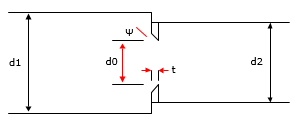
Figure 137 Bevel Edged Orifice in a Transition Section (Contraction)
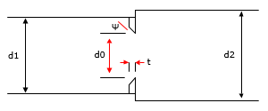
Figure 138 Bevel Edged Orifice in a Transition Section (Expansion)
The loss coefficient (K0) of a bevel edged orifice in a transition section is calculated as follows:
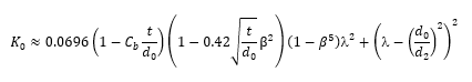
Where the diameter ratio β = d0/d1 and where the jet contraction coefficient is given by:
And where Cb is a function of bevel angle ψ in degrees, and bevel thickness to diameter ratio t/d0 is given by:
Bevel Edged Orifice Discharging To Atmosphere
A bevel edged orifice that discharges to atmosphere is illustrated in Figure 139.
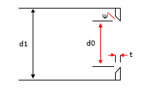
Figure 139 Bevel Edged Orifice Discharging to Atmosphere
For this orifice configuration, the loss coefficient (K0) equation for a bevel edged orifice in an expanding transition section can be used, however the downstream pipe diameter (d2) is effectively infinite and therefore the equation can be transformed into:
Where the diameter ratio β = d0/d1 and where the jet contraction coefficient is given by:
And where Cb is a function of bevel angle ψ in degrees, and bevel thickness to diameter ratio t/d0 is given by:
Thick Edged Orifice in a Straight Pipe
A thick edged orifice in a straight pipe, where the upstream and downstream pipe sizes are the same, is illustrated in Figure 140.
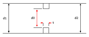
Figure 140 Thick Edged Orifice in a Straight Pipe
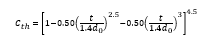
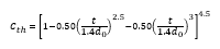
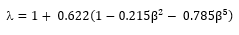
The loss coefficient (K0) of local resistance for thickness t equal to or less than 1.4d of a thick edged orifice in a straight pipe is calculated as follows:
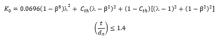
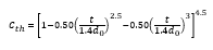
Where the diameter ratio β = d0/d1 and where the jet contraction coefficient is given by:
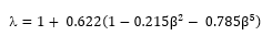
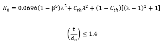
And where Cth is given by:
Thick Edged Orifice in a Transition Section
A thick edged orifice in a transition section, where the upstream and downstream pipe sizes are not the same, are illustrated in Figure 141 and Figure 142.
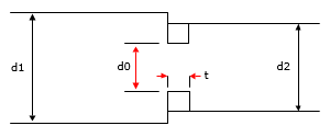
Figure 141 Thick Edged Orifice in a Transition Section (Contraction)
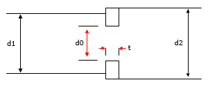
Figure 142 Thick Edged Orifice in a Transition Section (Expansion)
The loss coefficient (K0) of a thick edged orifice in a transition section is calculated as follows:
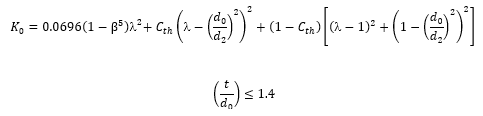
Where the diameter ratio β = d0/d1 and where the jet contraction coefficient is given by:
And where Cth is given by:
Thick Edged Orifice Discharging to Atmosphere Section
A thick edged orifice that discharges to atmosphere is illustrated in Figure 143.

Figure 143 Thick Edged Orifice Discharging to Atmosphere
For this orifice configuration, the loss coefficient (K0) equation for a thick edged orifice in an expanding transition section can be used, however the downstream pipe diameter (d2) is effectively infinite and therefore the equation can be transformed into:
Where the diameter ratio β = d0/d1 and where the jet contraction coefficient is given by:
And where Cth is given by: