How do I model a Three Way Valve within a Pipe Flow Expert system?
Modeling a 3-Way Valve
The Pipe Flow Expert software does not contain a three way valve as a standard item, however, it is possible to model a 3-way valve using a component and two flow control valves (FCVs).
Components with a Kv value:
If you have a valve with a Kv value (or Cv value) for a particular valve position, such as fully open then you can add a Component to a pipe and specify the component to operate from a Kv value. The software will then balance the system, showing the flow through the valve and the pressure loss across the valve when considering all of the other flows and pressures in the system.
Note: A Kv value is typically associated with a valve. The Kv flow coefficient value specifies the volume of water in m3/hour at 20°C (68 °F) that will flow through the valve with a 1.0 bar pressure drop across the valve. If a valve has different Kv values for various open positions, you will need to update the Kv value in the component to match the valve position you are considering before solving the network.
FCVs to control flow rates:
You can use a flow control valve (FCV) to specify a required flow rate and when the system is solved the software calculates what pressure drop the FCV needs to introduce in order to get the specified flow rate in the pipe when considering all of the other flows and pressures throughout the system.
To control the flow rate along a particular path in your system, place an FCV on a pipe and specify the required flow rate. When the system is solved, Pipe Flow Expert will report the pressure loss introduced by the FCV to control the flow to the specified rate. From this information, you can calculate a Cv or Kv value, and then you can select an appropriate balancing valve from a manufacturer’s catalogue, which can be used in the actual installation.
THREE WAY VALVE MODELLING:
It is necessary to use two FCVs to model the different flow rates that occur through the three way valve.
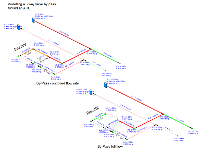
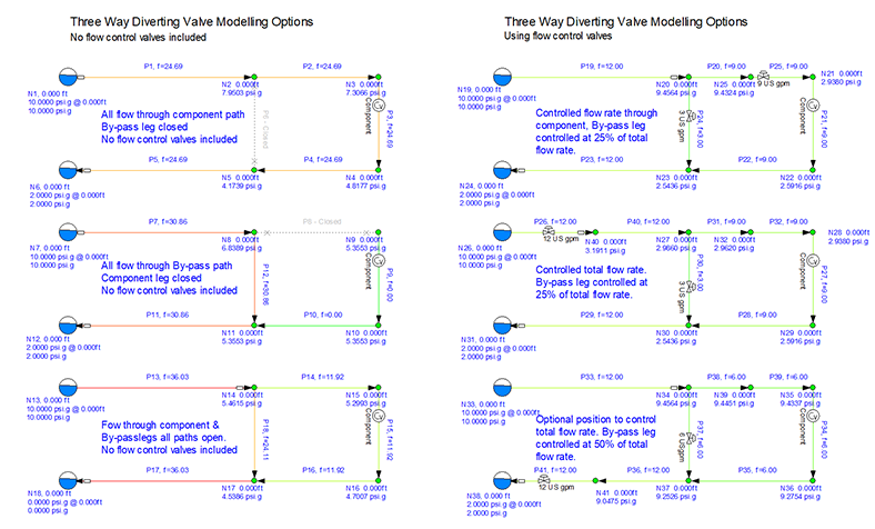
Typically, the total flow expected to pass through the valve is controlled by an FCV placed on the pipe entering or exiting the valve on the main flow path. A second FCV should be placed on the pipe of by-pass valve loop to model the flow rate through the bypass. Thus it is only necessary to change the by-pass flow value to model different situations for most by-pass flows.
If all the flow is required through the by-pass leg, it will usually be necessary to ‘remove’ the FCV on the by-pass and close one of the pipes in the normal flow loop.
We include an example of this option shown below:

When using a FCV you are controlling the flow and these items cannot be used in series or used with other flow controlling items in series, such as fixed flow pumps and flow demands. We would always recommend including one flow control valve on the by pass line and one on the main line to avoid conflicts between adjacent FCVs.
Note: Pipe Flow Expert modelling does not allow a FCV on pipe which connects to a pipe which already contains a flow control device. A pipe may need to be split into two sections to allow a FCV to be added.
Adding the FCV allows you to fix the flow rate and the software will then calculate the pressure drop across the valve. You can then use this data to define a component with a Cv or Kv value that will produce the same pressure loss for the same flow rate using Pipe Flow Expert's built in Cv and Kv calculator helper. You can then include the Cv component in place of the FCV on the pipe if this is preferred.
Examples of this modelling option are given in the system comparisons below.


