Common Gas 03 – Pipe Fittings and Valves

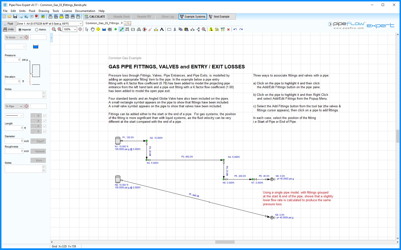
Figure 46 Common Gas 03 – Pipe Fittings and Valves
Pressure loss through Fittings (bends, contractions, expansions, tank entrances, tank exits) and Valves is modelled by adding these items on to a pipe. In the example below a pipe entry K factor flow coefficient (0.78) has been added to model the projecting pipe entrance fitting from the left hand tank and a pipe exit K factor flow coefficient (1.00) has been added to model the open pipe exit.
Four Standard Bends and an Angled Globe Valve have also been added on to the pipes.
A small rectangle symbol appears on the pipe to show that fittings have been included.
A small valve symbol appears on the pipe to show that valves have been included.
Fittings can be added either at the start or the end of a pipe. For gas systems, the position of the fitting is more significant than with liquid systems, since the fluid velocity can be very different at the start and end of a pipe.

