Case 06: Gas Pipeline Outlet Pressure vs Length
Reference: Gas Pipeline Hydraulics, 2005, CRC Press, E. Shashi Menon Chapter 2, page 80
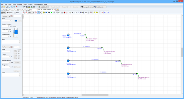
Pipe Flow Expert File: Case_06_Outlet_Pressure_vs_Length.pfe
Problem Description:
For a 100 mile long gas pipeline, 15.5 inch internal diameter, use different flow equations to compare the outlet pressure at points 25 miles, 50 miles, 75 miles and 100 miles downstream from the start of the pipe for a gas flow rate of 100 MMSCFD.
The gas temperature is 80 °F, and the upstream pressure at the start of the pipe is fixed at 1400 psi.g.
The published data uses 5 different calculation methods for comparison: Panhandle A, Panhandle B, General with Colebrook-White, AGA and Weymouth. For details of pipeline efficiency and gas compressibility see comments in results table.

Pipe Flow Expert Parameters:
Fluid Data: Gas specific gravity 0.6 (0.044 lb/ft3), 80 °F, 0.00 psi.g, viscosity 0.0119 centipoise.
Pipe Data: Roughness 700 micro-inches
Calculation Method: Various Isothermal flow equations, Node Adjust Method.
Standard Atmospheric Model: 60 °F, 14.696 psi.a
Gas Physical Model: Real Gas Model (Ideal Gas Law with CNGA compressibility factor).
A pipeline efficiency value of 0.95 was used in the Panhandle and Weymouth equations.
The General Fundamental Isothermal Flow equation used Colebrook-White friction factors.
The CNGA compressibility factor was used with all isothermal flow equations except for the AGA Ideal Gas Case.
Result Comparison:
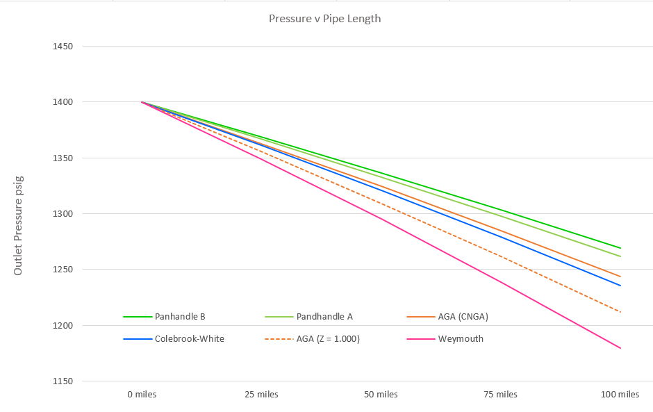
Published Graph Readings of Outlet Pressures (Psi.g):
|
Formula |
Panhandle B |
Panhandle A |
General Colebrook-White |
AGA |
AGA Ideal Gas |
Weymouth |
|
Friction |
Effic. = 0.95 |
Effic. = 0.95 |
IR =0.0007in |
IR =0.0007in |
IR =0.0007in |
Effic. = 0.95 |
|
Assumed Compressibility |
CNGA factor |
CNGA factor |
CNGA factor |
CNGA factor |
Ideal gas Z = 1.000 |
CNGA factor |
|
25 miles |
1368 |
1365 |
1359 |
Not available |
1353 |
1345 |
|
50 miles |
1335 |
1330 |
1318 |
Not available |
1305 |
1289 |
|
75 miles |
1303 |
1295 |
1276 |
Not available |
1258 |
1234 |
|
100 miles |
1270 |
1260 |
1235 |
Not available |
1210 |
1178 |
Pipe Flow Expert Calculated Results of Outlet Pressures (Psi.g):
|
Formula |
Panhandle B |
Panhandle A |
General Colebrook-White |
AGA |
AGA Ideal Gas |
Weymouth |
|
Friction |
Effic. = 0.95 |
Effic. = 0.95 |
IR =0.0007in |
IR =0.0007in |
IR =0.0007in |
Effic. = 0.95 |
|
Compressibility |
CNGA factor |
CNGA factor |
CNGA factor |
CNGA factor |
Ideal gas Z = 1.000 |
CNGA factor |
|
25 miles |
1368.7 |
1366.9 |
1361 |
1362.8 |
1355.4 |
1348.7 |
|
50 miles |
1336.5 |
1332.9 |
1320.7 |
1324.4 |
1309.2 |
1295.1 |
|
75 miles |
1303.4 |
1297.9 |
1278.9 |
1284.7 |
1261.4 |
1238.8 |
|
100 miles |
1269.3 |
1261.7 |
1235.5 |
1243.5 |
1211.7 |
1179.4 |
Graphical Comparison of Formula:

Commentary:
The published results specified a pipe roughness (700 μ inches) for use in both the AGA & General Flow equations (with Colebrook-White friction factors) and a pipeline efficiency of 0.95 for used in the Panhandle & Weymouth equations. Reference to IR=0.0007in in the above tables means an internal roughness of 700 μ inches.
The published data did not specify if a compressibility factor had been used in the calculations, however most of the other example calculations in the published work included a compressibility factor. In the Pipe Flow Expert software, the CNGA (Californian Natural Gas Association) method for automatic calculation of the compressibility factor was selected. The calculated results compare well with the published graph readings, indicating that a compressibility factor was used in the calculation of the published data for all equations except the published AGA results, which appear to have been based on assumption of the Ideal Gas Law with no compressibility.

