Case 12: Parallel Pipes: Pressures at Nodes
Reference: Gas Pipeline Hydraulics, 2005, CRC Press, E. Shashi Menon, Chapter 3, page 116 Example 7
Pipe Flow Expert File: Case_12_Parallel_Pipes.pfe
Problem Description:
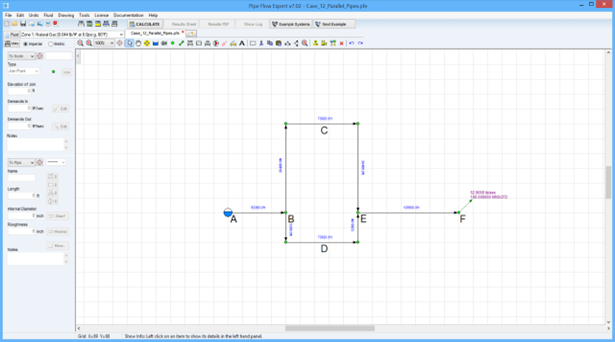
A gas pipeline consists of two parallel pipes, as shown in the screen image below, designed to operate at a flow rate of 100 MMSCFD.
Pipe segment AB is 12 miles long, consisting of a pipe with an internal diameter of 15.5 inches.
The loop BCE is 24 miles long with pipes of 13.5 inches internal diameter.
The loop BDE is 16 miles long with pipes of 12.25 inches internal diameter.
The pipe segment EF is 20 miles long, consisting of a pipe with internal diameter 15.5 inches.
Assuming a gas gravity of 0.6, calculate the outlet pressure at F and the pressures at the beginning and end of the pipe loops and the flow rates through them.
The inlet pressure at A is 1200 psi.g, and the gas flowing temperature is 80 °F.
Use a compressibility factor of 0.92.
The calculation method used for the published data was the General Flow equation.

Pipe Flow Expert Parameters:
Fluid Data: Gas with specific gravity 0.6 (0.044 lb/ft3), 80 °F, 0.00 psi.g, viscosity 0.0119 centipoise.
Pipe Data: Roughness 0.004 inches for all pipes.
Calculation Method: General Isothermal Flow equation, Node Adjust Method.
Standard Atmospheric Model: 60 °F, 101.325 kPa.
Gas Physical Model: Real Gas Model (Ideal Gas Law with compressibility factor Z=0.92).
Result Comparison:
|
Data Item |
Published data |
Pipe Flow Expert |
|
Flow rate BCE (MMSCFD) |
51.0 |
51.2 |
|
Flow rate BDE (MMSCFD) |
49.0 |
48.8 |
|
Pressure at B (psi.g) |
1166.6 |
1167.6 |
|
Pressure at E (psi.g) |
1130.9 |
1131.5 |
|
Pressure at F (psi.g) |
1071.12 |
1073.6 |
Commentary:
The published data and the calculated results compare well. The roughness value used of 0.004 gave a friction factor of around 0.015 for all pipes, as per the published results.

