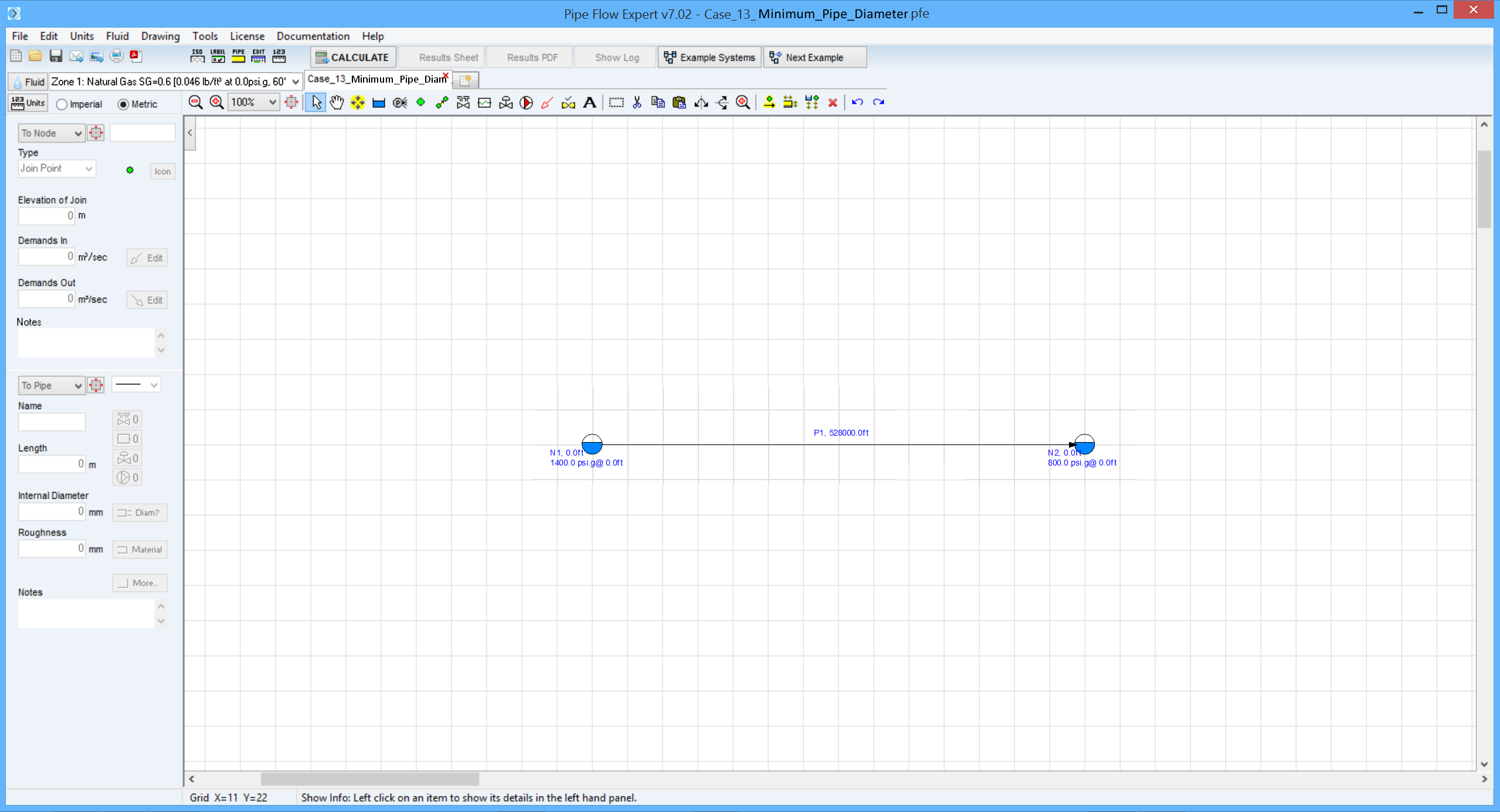
Case 13: Minimum Pipe Diameter
Reference: Gas Pipeline Hydraulics, 2005, CRC Press, E. Shashi Menon, Chapter 3, page 97 Example 3
Pipe Flow Expert File: Case_13_Minumum_Pipe_Diameter.pfe
Problem Description:
A pipeline 100 miles long transports natural gas, at a constant temperature of 60°F.
The inlet pressure is 1400 psi.g and the delivery pressure required is 800 psi.g.
The required flowrate is 100 MMSCFD.
Find the minimum pipe diameter needed using the AGA, General with Colebrook-white, Panhandle B and Weymouth equations.
Use a compressibility factor of 0.9 and a 95% pipeline efficiency where appropriate.
The pipe roughness is 700 micro inches.

Pipe Flow Expert Parameters:
Fluid Data: Gas with specific gravity 0.6 (0.0458 lb/ft3), 60 °F, 0.00 psi.g, viscosity 0.0119 centipoise.
Pipe Data: Pipe roughness 0.000700 inches.
Calculation Method: AGA, General Flow, Panhandle B and Weymouth equations, Node Adjust Method.
Standard Atmospheric Model: 60°F, 14.696 psi.a
Gas Physical Model: Real Gas Model (Ideal Gas Law with compressibility factor Z=0.90).
Result Comparison:
|
Data Item |
Published data |
Equation |
Pipe Flow Expert |
Pipe Flow Expert Flow Rate |
|
Pipe diameter |
12.47 inches |
AGA |
12.463 inches |
100.043 MMSCFD |
|
Pipe diameter |
12.55 inches |
General |
12.538 inches |
100.044 MMSCFD |
|
Pipe diameter |
11.93 inches |
Panhandle B |
11.931 inches |
100.034 MMSCFD |
|
Pipe diameter |
13.30 inches |
Weymouth |
13.305 inches |
100.012 MMSCFD |
Commentary:
The published data and the calculated results compare well.
Colebrook-white refers to the method used to calculate friction factors in the General Isothermal Flow equation.
The pipe diameter was amended in the Pipe Flow Expert model for each of the equations selected, until the flow rate obtained was just in excess of 100 MMSCFD. The pipe diameter iteration took only 2 or 3 adjustments to obtain the results above.

