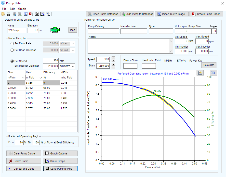
Adding a Fixed Speed Pump Curve
To add a fixed speed pump to a pipe:
- Add a pump to a pipe (as described in the previous Adding a Pump section).
- The pump is positioned at the start of the pipe, immediately after any fittings that are included at the start of the pipe. The Elevation field is automatically populated and set to be the same as the elevation of the node at the start of the pipe. Click the Icon button to select the pump symbol you want displayed on the pipe system drawing.
- Type the pump’s name in the Name field.
- Click the Set Speed radio button.
- Type the pump’s number of rotations per minute (rpm) in the Speed field.
- Choose the diameter units and enter the pump impeller diameter (if applicable).
- Select the applicable units for the pump curve from the Flow and Head drop down lists.
- Determine the points from the manufacturer’s pump graph that you wish to include on the Pump Curve graph, and enter the head, efficiency and NPSHr values for each of these points in the Pump Curve section of the Pump Data performance table.
- Add a minimum of 4 and maximum of 10 points to the Pump Curve section.

- Type Define the Preferred Operating Region around the pump’s best efficiency point by specifying the preferred flow rate range between a From percentage and a To percentage of the flow at the best efficiency point.
- Once the operating points have been entered, click the ‘Draw Graph’ button to produce an operating curve for the pump.
- Click the Save Pump to Pipe to add the pump data to the Pipe Flow Expert system.
- The system can now be solved and the balanced operating point of the centrifugal pump will be determined.
- The pump will produce a flow rate and pump head to match the frictional resistance throughout the system. The duty point will be identified on the performance curve for the operating speed of the pump
.
- More complex pump graphs can be produced which include speed & diameter adjustments, together with iso lines that display an efficiency map for the pump.
- The pump data that has been entered can be saved to a Standalone Pump File with a pfpm extension by clicking the Save button on the toolbar on the pump screen or by selecting the Save Standalone Pump File from the pump screen file menu options.
- By saving the data to a Standalone Pump File (with a .pfpm extension), you can reuse the pump data for other pumps in the pipe system or future pipe systems.
- To add a pump’s data using an existing .pfpm file, click the Load Pump from File button or select the Load Standalone Pump File from the pump screen menu options. Select the applicable .pfpm file, click Open, edit the applicable fields, and then click the Save Pump to Pipe button.
When a pump is added to a pipe, the Include check box is displayed and set as selected, next to the Add/Change Pump button,  .
.
When the Include check box is selected, Pipe Flow Expert includes the data from the pumps on the pipe in the calculations for solving the pipe system. To remove the pump data from the calculations, clear the Include check box.
