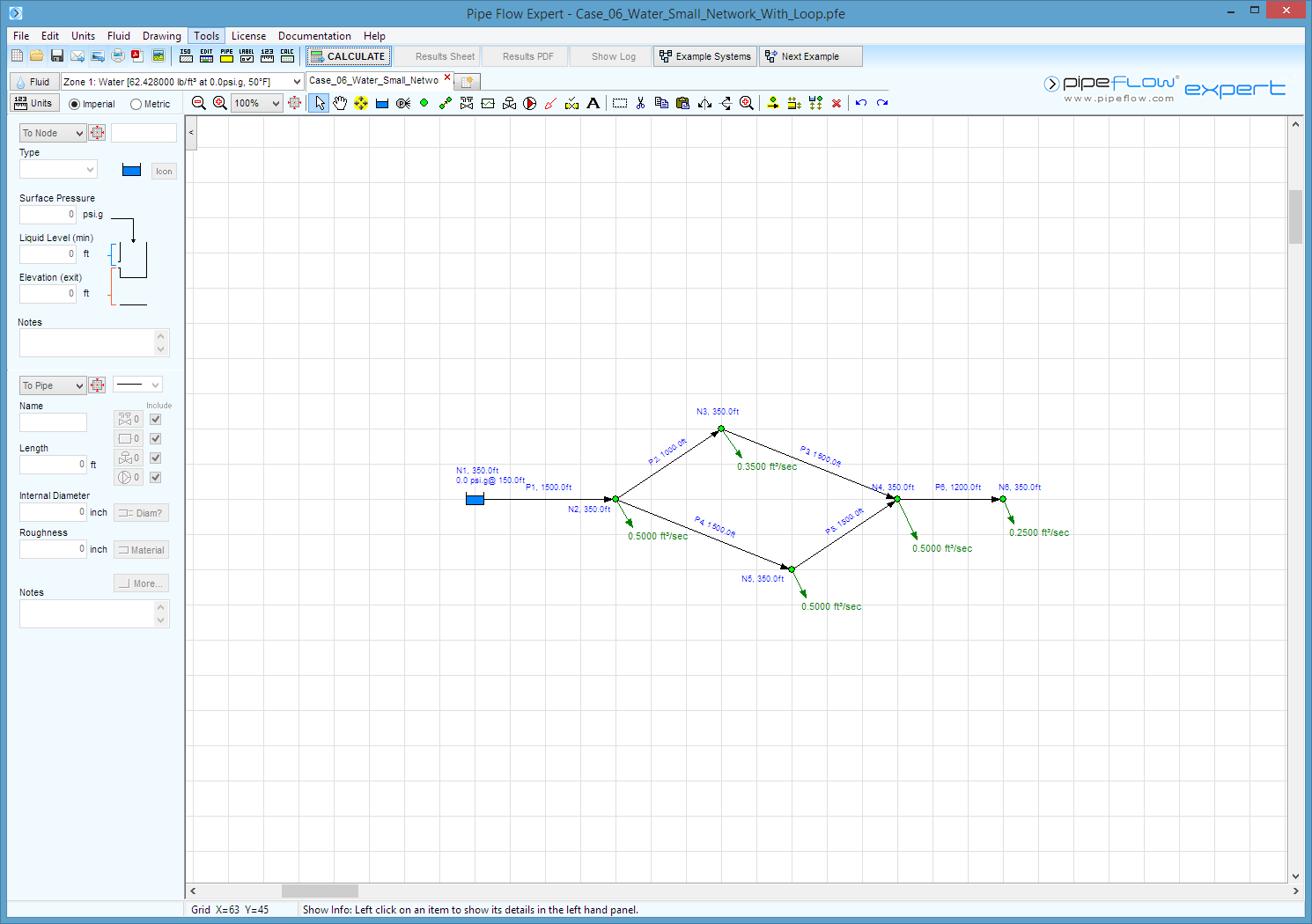
Case 06: Water - Small Network with Loop
Reference: Hydraulics of Pipeline Systems, 2000, CRC Press LLC, Bruce E. Larock, Rowland W. Jeppson, Gary Z. Watters, Page 185, Example problem 5.5.2
Pipe Flow Expert File: Case_06_Water_Small_Network_With_Loop.pfe
Problem Description:
A small pipe network comprises 6 Cast Iron (Asphalt Dipped) pipes.
A water source has a surface elevation of 500 ft.
At each node in the pipe network water is removed from the system.
Calculate the flow rate and head loss in each pipe.
Calculate the pressure and Hydraulic Grade Line at each node.

Fluid Data: Water at 50° F. (Assumed)
Result Comparison:
|
Pipe |
Published Flow (ft³/s) |
Pipe Flow Expert (ft³/s) |
|
Pipe |
Published Head Loss (ft) |
Pipe Flow Expert Head Loss (ft) |
|
Pipe 1 |
2.100 |
2.1000 |
|
Pipe 1 |
23.95 |
23.96 |
|
Pipe 2 |
0.824 |
0.8244 |
|
Pipe 2 |
11.39 |
11.40 |
|
Pipe 3 |
0.474 |
0.4744 |
|
Pipe 3 |
5.98 |
5.97 |
|
Pipe 4 |
0.776 |
0.7756 |
|
Pipe 4 |
15.21 |
15.21 |
|
Pipe 5 |
0.276 |
0.2756 |
|
Pipe 5 |
2.17 |
2.16 |
|
Pipe 6 |
0.249 |
0.2500 |
|
Pipe 6 |
10.94 |
10.94 |
|
Node |
Published Press. (lb/in²) |
Pipe Flow Expert Press. (lb/in²) |
|
Node |
Published data HGL. (ft) |
Pipe Flow Expert HGL. (ft) |
|
N1 |
n/a |
n/a |
|
N1 |
500.0 |
500.00 |
|
N2 |
54.6 |
54.6424 |
|
N2 |
476.0 |
476.04 |
|
N3 |
49.7 |
49.7020 |
|
N3 |
464.7 |
464.65 |
|
N4 |
47.1 |
47.1120 |
|
N4 |
458.7 |
458.67 |
|
N5 |
48.0 |
48.0499 |
|
N5 |
460.8 |
460.83 |
|
N6 |
42.4 |
42.3693 |
|
N6 |
447.7 |
447.73 |
Commentary:
The published data and the calculated results compare very well.

