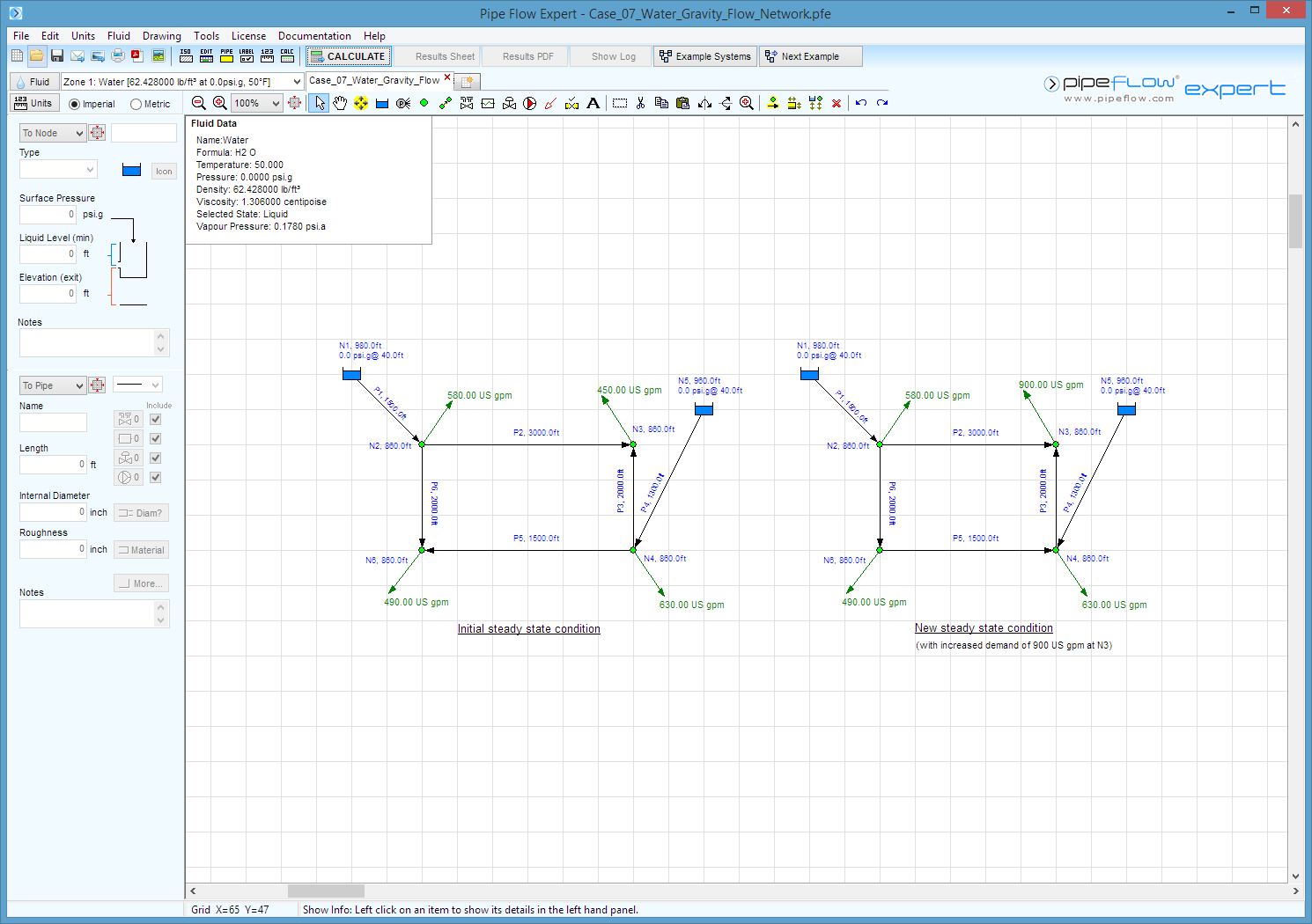
Case 07: Water - Gravity Flow Network - Initial and Increased Demands
Reference: Hydraulics of Pipeline Systems, 2000, CRC Press LLC, Bruce E. Larock, Rowland W. Jeppson, Gary Z. Watters, Page 437, Example problem 12.4
Pipe Flow Expert File: Case_07_Water_Gravity_Flow_Network.pfe
Problem Description:
Water is supplied from two elevated reservoirs to various outlet points in a pipe network. Initially the outflow demands of the network are 580 gpm, 450 gpm, 630 gpm and 490 gpm.
A new situation arises where the demand at one outflow point must be increased from 450 gpm to 900 gpm to meet a need for fire suppression.
1. For the initial flow condition calculate the flow rate and head loss for each pipe, the pressure and HGL (Hydraulic grade line) at each node point.
2. When the additional flow is being supplied to meet the fire suppression requirement calculate the pressure at the node where the 900 gpm leaves the network.

Fluid Data: Water at 50° F (assumed).
Result Comparison:
|
Pipe |
Published Flow ( gpm) |
Pipe Flow Expert ( gpm) |
|
Pipe |
Published Head Loss (ft) |
Pipe Flow Expert Head Loss (ft) |
|
Pipe 1 |
1447.0 |
1446.88 |
|
Pipe 1 |
15.61 |
15.61 |
|
Pipe 2 |
389.0 |
388.82 |
|
Pipe 2 |
8.08 |
8.08 |
|
Pipe 3 |
61.2 |
61.18 |
|
Pipe 3 |
0.19 |
0.19 |
|
Pipe 4 |
703.0 |
703.12 |
|
Pipe 4 |
3.49 |
3.50 |
|
Pipe 5 |
11.7 |
11.95 |
|
Pipe 5 |
0.02 |
0.01 |
|
Pipe 6 |
478.0 |
478.05 |
|
Pipe 6 |
7.90 |
7.90 |
|
Node |
Published Press. (lb/in²) |
Pipe Flow Expert Press. (lb/in²) |
|
Node |
Published data HGL. (ft) |
Pipe Flow Expert HGL. (ft) |
|
N1 |
17.33 |
17.3411 |
|
N1 |
1020.0 |
1020.00 |
|
N2 |
62.57 |
62.5911 |
|
N2 |
1004.4 |
1004.39 |
|
N3 |
59.07 |
59.0947 |
|
N3 |
996.3 |
996.31 |
|
N4 |
59.15 |
59.1776 |
|
N4 |
996.5 |
996.50 |
|
N5 |
17.33 |
17.3411 |
|
N5 |
1000.0 |
1000.00 |
|
N6 |
59.15 |
59.1740 |
|
N6 |
996.5 |
996.49 |
Commentary:
The published data and the calculated results compare very well.
The full analytical results for situation where the increased flow rate of 900 gpm is delivered are not published, however the text notes that the new pressure head at the outlet point with this increased flow rate has fallen to 127.8 ft.
When the increased outlet flow is occurring, the flow direction in pipe P5 will be reversed due to the change in pressures at N4 and N6.
Pipe Flow Expert reports the new pressure at N3 as 127.80 ft.
This result agrees with the published text.

