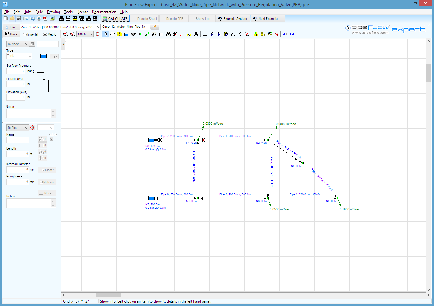
Case 42: Water - Nine Pipe Network with Pressure Regulating Valve(PRV)
Reference: Hydraulics of Pipeline Systems, 2000, CRC Press LLC, Bruce E. Larock, Rowland W. Jeppson, Gary Z. Watters, Page 106, Example problem 4.9
Pipe Flow Expert File: Case_42_Water_Nine_Pipe_Network_With_Pressure_Regulating_Valve(PRV).pfe
Problem Description:
A network of 9 interconnected pipes delivers water from two reservoirs to outlet demands at various pipework junctions.
The network includes 2 pumps, two globe valves and a meter.
The network has two closed loops and one open loop.
The pressure at a node 8 is controlled by a pressure regulating valve set to 14.5827 psig (equivalent to 149 m head of water as specified in the example text).
Calculate the flow rate in each individual pipe and the pump heads added to the system.

Fluid Data: Water at 20° C (assumed).
Result Comparison:
|
Data Item |
Published data |
Pipe Flow Expert |
|
Q1 Flow rate (m³/s) |
0.1125 |
0.1131 |
|
Q2 Flow rate (m³/s) |
-0.0018 |
0.0003 (pipe reversed) |
|
Q3 Flow rate (m³/s |
0.1175 |
0.1169 |
|
Q4 Flow rate (m³/s |
0.0792 |
0.0772 |
|
Q5 Flow rate (m³/s |
0.0343 |
0.0328 |
|
Q6 Flow rate (m³/s |
0.0657 |
0.0672 |
|
Q7 Flow rate (m³/s |
0.0633 |
0.0659 |
|
Q8 Flow rate (m³/s) |
0.1967 |
0.1941 |
|
Q9 Flow rate (m³/s) |
0.0343 (same as Q5) |
0.0328 |
|
Pump 1 - head added |
6.18 m fluid |
6.183 m fluid |
|
Pump 2 - head added |
3.58 m fluid |
3.593 m fluid |
|
HGL at PRV Node |
149.000 m |
149.000 m |
Commentary:
The published data and the calculated results compare well.
Pipe Flow Expert correctly identified that pipe 2 was drawn with the wrong flow direction in the design schematic. This pipe was reversed and the flow was reported as positive value.
The reference text reports flow as negative values where an incorrect flow direction has been assumed.

