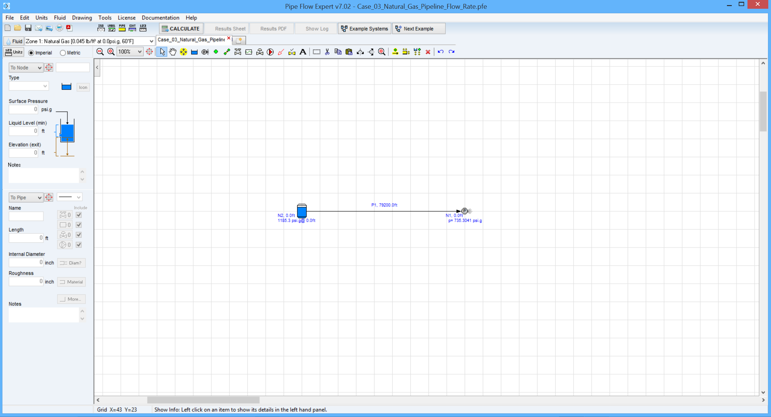
Case 03: Gas Pipeline Flow Rate
Reference: Gas Pipeline Hydraulics, 2005, CRC Press, E. Shashi Menon Chapter 2, page 62 Example 13
Pipe Flow Expert File: Case_03_Natural_Gas_Pipeline_Flow_Rate.pfe
Problem Description:
Calculate the flow rate in a gas pipeline system, 15 miles long, with a 12.25 inch internal pipe diameter. Upstream pressure is 1200 psi absolute and the delivery pressure required at the end of the pipe is 750 psi absolute.
Pipe roughness is 700 micro-inches. Use a compressibility factor of 0.94 and a pipeline efficiency of 0.95.
The calculation methods used for the published data were:
- Weymouth equation
- General Flow equation

Pipe Flow Expert Parameters:
Fluid Data: Gas specific gravity 0.59 (0.044 lb/ft3) at 75 °F, 0.0 bar.g, viscosity 0.0119 centipoise.
Pipe Data: Roughness 700 micro-inches.
Calculation method: Weymouth equation, General Flow Equation, Node Adjust Method.
Standard Atmospheric Model: 60°F, 14.696 psi.
Gas Physical Model: Real Gas Model (Ideal Gas Law with compressibility factor Z=0.94).
Result Comparison:
|
Data Item |
Published data |
Pipe Flow Expert |
|
Gas flow rate (Weymouth equation, MMSCFD) |
163.26 |
163.18 |
|
Gas flow rate (General Flow equation, MMSCFD) |
192.98 |
192.98 |
Commentary:
The published data and the calculated results compare well. It can be seen that the results from the Weymouth equation are quite conservative.

