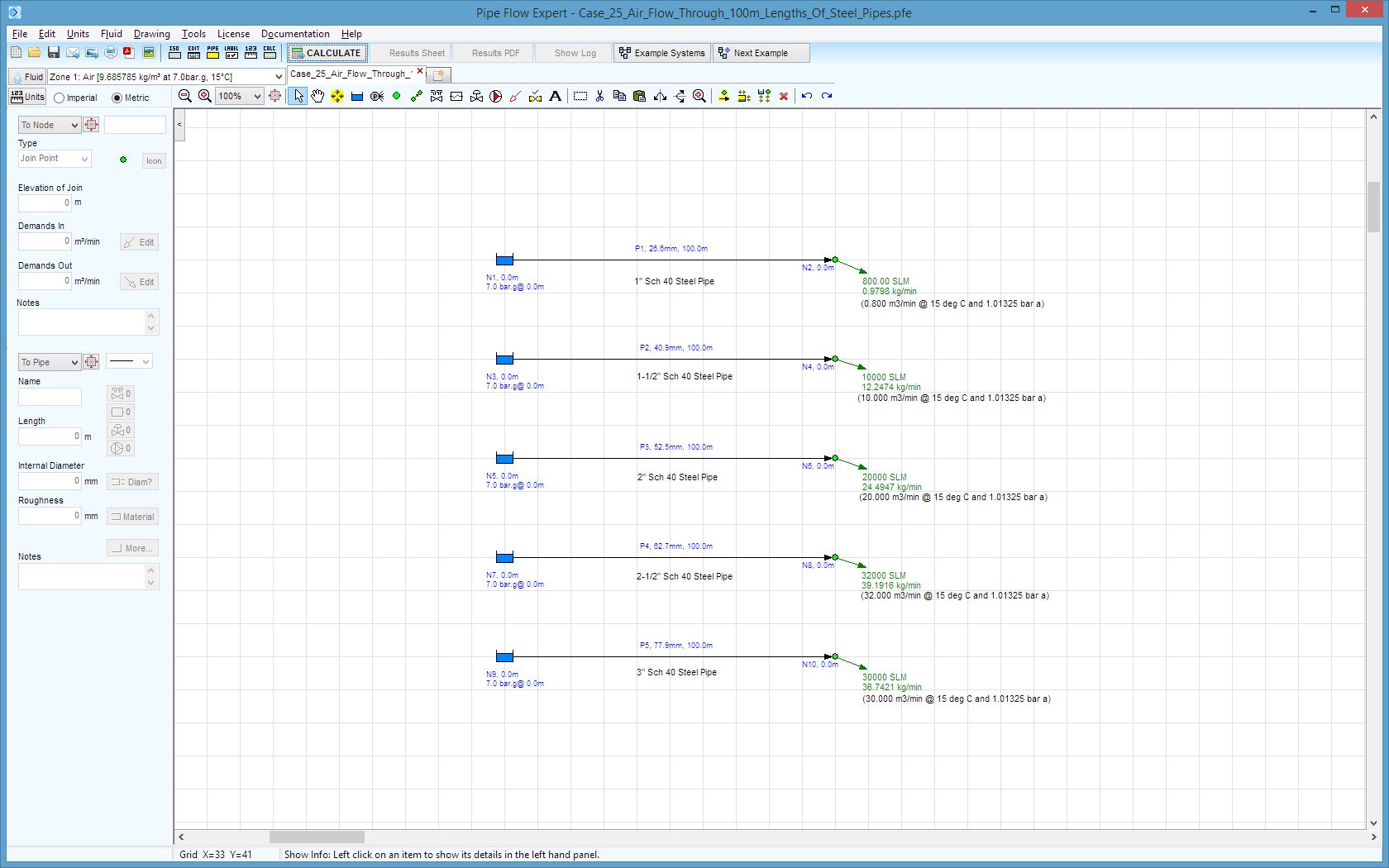
Case 25: Air – Flow Through 100m Lengths of Steel Pipes
Reference: Flow of Fluids – Technical Paper No 410M, 1999, Crane Co. Appendix B-14.
Pipe Flow Expert File: Case_25_Air_Flow_Through_100m_Lengths_Of_Steel_Pipes.pfe
Problem Description:
Compressed air at 7 bar gauge and 15°C flows through 100 meter long schedule 40 steel pipes.
Find the pressure drop in each of the pipes.

Fluid Data: Air at 15 °C, 7.0 bar.g, density 9.685785 kg/m3, viscosity 0.018069 centipoise.
Pipe Data: Internal diameters of standard Schedule 40 Steel pipe, various sizes. Roughness 0.046 mm.
Calculation method: General Isothermal Flow equation, Node Adjust Method.
Standard atmospheric model: 15 °C, 101.325 kPa absolute
Gas physical model: Ideal Gas Law
Result Comparison:
|
Pipe Details |
Free Air m³/min |
Compressed Flow m³/min |
Published Pressure Drop (Bar) |
Pipe Flow Expert Pressure Drop (Bar) |
|
1.0” Diameter Schedule 40 Steel Pipe, 100 m long |
0.800 |
0.101 |
0.044 |
0.0438 |
|
1-1/2” Diameter Schedule 40 Steel Pipe, 100 m long |
10.000 |
1.264 |
0.640 |
0.6673 |
|
2.0” Diameter Schedule 40 Steel Pipe, 100 m long |
20.000 |
2.528 |
0.685 |
0.7180 |
|
2-1/2” Diameter Schedule 40 Steel Pipe, 100 m long |
32.000 |
4.046 |
0.682 |
0.7226 |
|
3.0” Diameter Schedule 40 Steel Pipe, 100 m long |
30.000 |
3.793 |
0.197 |
0.2004 |
Commentary:
The published data and the calculated results compare well but differ slightly, with pressure drop comparisons varying by up to 0.04 bar (or about 5.5% of the total pressure drop).
The published data was read from tabulated results, for various pipe sizes and flow rates, which we believe were calculated using the Darcy-Weisbach equation, since Pipe Flow Expert results produced with its non-compressible calculation engine generate almost exactly the same figures as the published data, whereas these Pipe Flow Expert results were generated using the General Fundamental Isothermal flow equation for compressible flow (which is better suited for air flow calculations).

