Case 52: Water - Round-edged Orifice Loss Coefficient in a Straight Pipe
Reference: Pipe Flow – A Practical and Comprehensive Guide, 2012, Publisher Wiley, Donald C. Rennels, Hobart M. Hudson, Chapter 13, Page 142
Pipe Flow Expert File: Case_52_Water_Round_Edged_Orifice_Straight_Pipe.pfe
Problem Description:
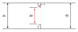
A straight pipe contains a round-edged single-hole orifice. Find the k0 loss coefficient for the orifice with a rounding radius specified as a ratio against the diameter of the orifice (r/d0).

Use different orifice diameter to pipe diameter ratios ( = d0/d), with varying degrees of rounding to compare the calculated loss coefficient (k0).
The published data uses different calculation methods for comparison:
Donald C. Rennels, Hobart M. Hudson Equation, Equation 13.6, ASME Fluid Meters, and Alvi et al.

Pipe Flow Expert Parameters:
Fluid Data: Water at, 68 °F
Pipe Data: Internal Diameter 4 inches, wall thickness 0.237 inches, roughness 1881 micro-inches
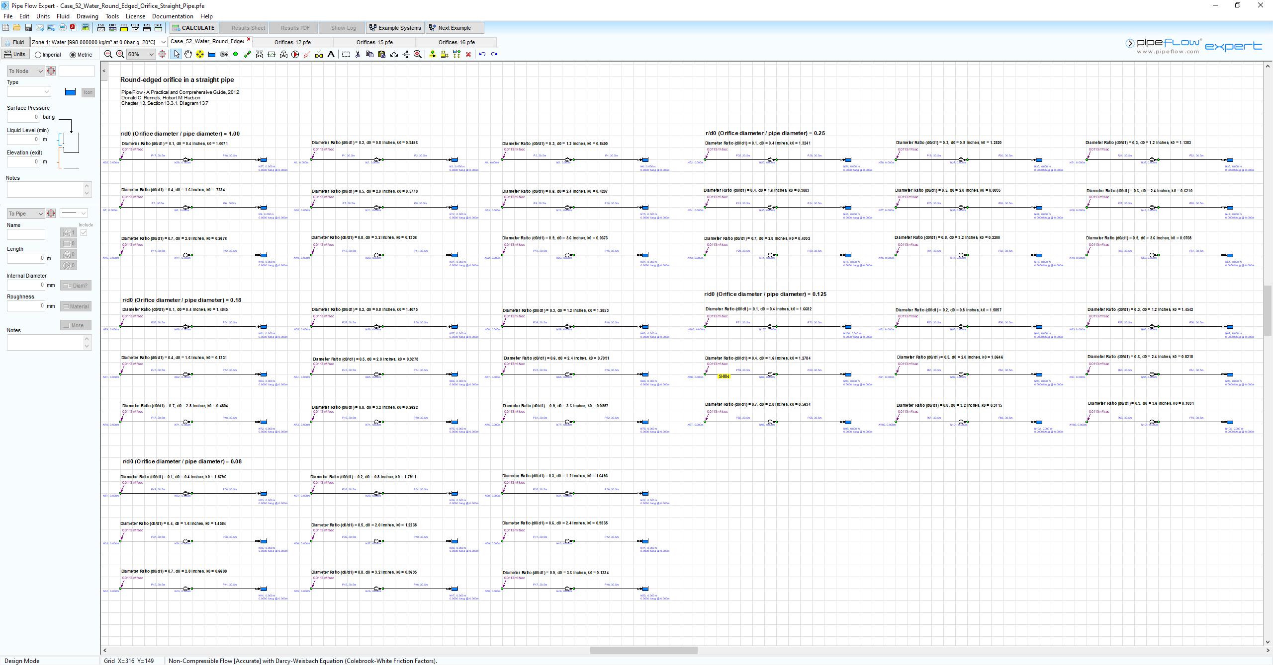
The following 45 systems with an inflow demand of 0.4 ft3/sec were used to model orifices with orifice / pipe diameter ratios ( = d0/d1) from 0.1 through to 0.9.
|
System # |
r/do (Rounding Radius / Orifice Diameter) |
|
1 – 9 |
1.00 |
|
10 – 18 |
0.25 |
|
19 – 27 |
0.18 |
|
28 – 36 |
0.125 |
|
37 – 45 |
0.08 |
Result Comparison:
Pipe Flow Expert Calculated Results and Published Graph Readings of Orifice Loss Coefficient (k0):
|
Orifice Diameter / Pipe Diameter (d0/d1) |
Rounding Radius / Orifice Diameter (r/d0) |
Donald C. Rennels, Hobart M. Hudson (k0) |
ASME Fluid Meters Low Flow Nozzle (k0) |
ASME Fluid Meters High Flow Nozzle (k0) |
Alvi et al. (k0) |
Pipe Flow Expert (k0) |
|
0.1 |
1.0 |
1.01 |
- |
- |
- |
1.01 |
|
0.2 |
1.0 |
0.95 |
0.95 |
- |
- |
0.95 |
|
0.3 |
1.0 |
0.85 |
0.86 |
- |
- |
0.85 |
|
0.4 |
1.0 |
0.72 |
0.74 |
- |
- |
0.72 |
|
0.45 |
1.0 |
- |
- |
0.68 |
- |
- |
|
0.5 |
1.0 |
0.58 |
0.61 |
- |
- |
0.58 |
|
0.6 |
1.0 |
0.42 |
- |
0.47 |
- |
0.42 |
|
0.7 |
1.0 |
0.27 |
- |
0.33 |
- |
0.27 |
|
0.8 |
1.0 |
0.13 |
- |
0.19 |
- |
0.13 |
|
0.9 |
1.0 |
0.04 |
- |
- |
- |
0.04 |
|
0.1 |
0.25 |
1.32 |
- |
- |
- |
1.32 |
|
0.2 |
0.25 |
1.25 |
- |
- |
1.255 |
1.25 |
|
0.3 |
0.25 |
1.14 |
- |
- |
- |
1.14 |
|
0.4 |
0.25 |
0.99 |
- |
- |
1.06 |
0.99 |
|
0.5 |
0.25 |
0.81 |
- |
- |
- |
0.81 |
|
0.6 |
0.25 |
0.62 |
- |
- |
0.625 |
0.62 |
|
0.7 |
0.25 |
0.41 |
- |
- |
- |
0.41 |
|
0.8 |
0.25 |
0.22 |
- |
- |
0.28 |
0.22 |
|
0.9 |
0.25 |
0.07 |
- |
- |
- |
0.07 |
|
0.1 |
0.18 |
1.48 |
- |
- |
- |
1.48 |
|
0.2 |
0.18 |
1.41 |
- |
- |
1.37 |
1.41 |
|
0.3 |
0.18 |
1.29 |
- |
- |
- |
1.29 |
|
0.4 |
0.18 |
1.12 |
- |
- |
1.12 |
1.12 |
|
0.5 |
0.18 |
0.93 |
- |
- |
- |
0.93 |
|
0.6 |
0.18 |
0.71 |
- |
- |
0.695 |
0.71 |
|
0.7 |
0.18 |
0.48 |
- |
- |
- |
0.48 |
|
0.8 |
0.18 |
0.26 |
- |
- |
0.31 |
0.26 |
|
0.9 |
0.18 |
0.09 |
- |
- |
- |
0.09 |
|
0.1 |
0.125 |
1.67 |
- |
- |
- |
1.67 |
|
0.2 |
0.125 |
1.59 |
- |
- |
1.57 |
1.59 |
|
0.3 |
0.125 |
1.45 |
- |
- |
- |
1.45 |
|
0.4 |
0.125 |
1.28 |
- |
- |
1.275 |
1.28 |
|
0.5 |
0.125 |
1.06 |
- |
- |
- |
1.06 |
|
0.6 |
0.125 |
0.82 |
- |
- |
.79 |
0.82 |
|
0.7 |
0.125 |
0.56 |
- |
- |
- |
0.56 |
|
0.8 |
0.125 |
0.31 |
- |
- |
- |
0.31 |
|
0.9 |
0.125 |
0.10 |
- |
- |
- |
0.10 |
|
0.1 |
0.08 |
1.88 |
- |
- |
- |
1.88 |
|
0.2 |
0.08 |
1.79 |
- |
- |
1.795 |
1.79 |
|
0.3 |
0.08 |
1.65 |
- |
- |
- |
1.65 |
|
0.4 |
0.08 |
1.46 |
- |
- |
1.465 |
1.46 |
|
0.5 |
0.08 |
1.22 |
- |
- |
- |
1.22 |
|
0.6 |
0.08 |
0.95 |
- |
- |
- |
0.95 |
|
0.7 |
0.08 |
0.66 |
- |
- |
- |
0.66 |
|
0.8 |
0.08 |
0.37 |
- |
- |
- |
0.37 |
|
0.9 |
0.08 |
0.12 |
- |
- |
- |
0.12 |
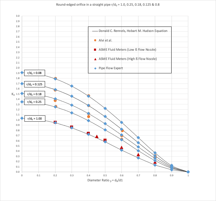
Graphical Comparison of Results:

Commentary:
The published k0 loss coefficients compare well with the calculated results.
Note: Head Loss in m fluid = (k0 * v2) / 2g
- where v = fluid velocity in m/s at the entrance to the orifice, g = acceleration due to gravity in m/s2
- k0 is not the same as a standard k value (which is used in formulas where v = velocity in the pipe)

