Case 53: Water - Thick-edged Orifice Loss Coefficient in a Straight Pipe
Reference: Pipe Flow – A Practical and Comprehensive Guide, 2012, Publisher Wiley, Donald C. Rennels, Hobart M. Hudson, Chapter 13, Page 146
Pipe Flow Expert File: Case_53_Water_Thick_Edged_Orifice_Straight_Pipe.pfe
Problem Description:
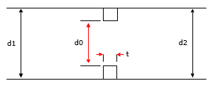
A straight pipe contains a thick-edged single-hole orifice. Find the k0 loss coefficient for the orifice with thickness specified as a ratio against the diameter of the orifice (t/d0).

Use different orifice thickness to orifice diameter ratios (t/d0) to compare the calculated orifice loss coefficient (k0) across a range of different orifice diameter to pipe diameter ratios.
The published data uses different calculation methods for comparison:
Donald C. Rennels, Hobart M. Hudson, Equation 13.13, James A.J., Sanderson E. W.

Pipe Flow Expert Parameters:
Fluid Data: Water at, 68 °F
Pipe Data: Internal diameter 4 inches, wall thickness 0.237 inches, roughness 1881 micro-inches
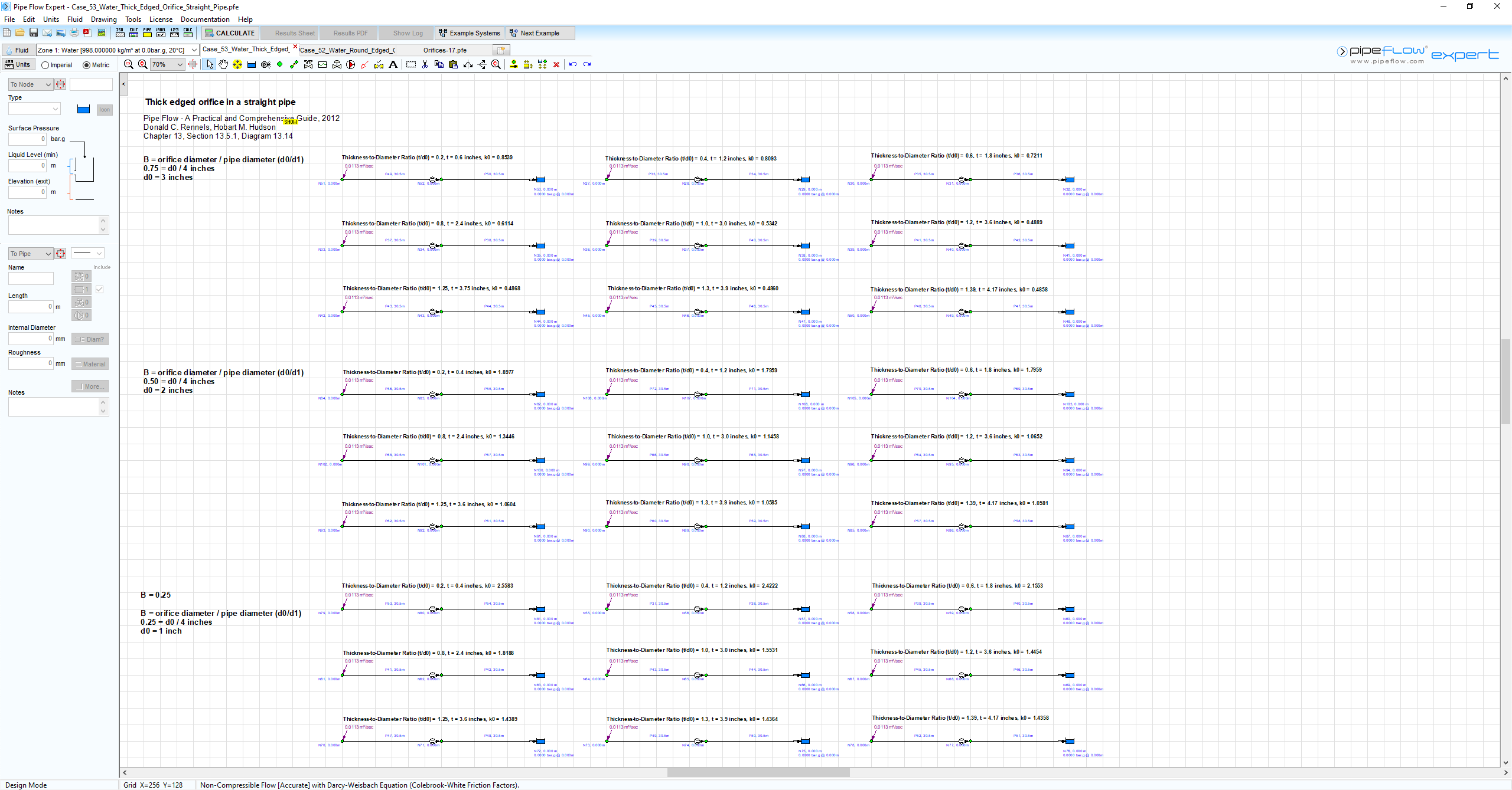
The following 27 systems, each with an inflow demand of 0.4 ft3/sec, were used to model orifices with a
thickness / diameter ratio (t/d0) ranging from 0.2 through to 2.0.
|
System # |
= d0/d1 (Orifice Diameter / Pipe Diameter) |
|
1 – 9 |
0.75 |
|
10 – 18 |
0.50 |
|
19 – 27 |
0.25 |
Result Comparison:
Pipe Flow Expert Calculated Results and Published Graph Readings of Orifice Loss Coefficient (k0):
|
Orifice Thickness / Orifice Diameter (t/d0) |
Orifice Diameter / Pipe Diameter ( = d0/d1) |
Donald C. Rennels, Hobart M. Hudson (k0) |
James |
Sanderson ( = 0.252) (k0) |
Pipe Flow Expert (k0) |
|
0.2 |
0.75 |
0.8539 |
- |
- |
0.8539 |
|
0.4 |
0.75 |
0.8093 |
- |
- |
0.8093 |
|
0.6 |
0.75 |
0.7211 |
- |
- |
0.7211 |
|
0.8 |
0.75 |
0.6114 |
- |
- |
0.6114 |
|
1.0 |
0.75 |
0.5243 |
- |
- |
0.5243 |
|
1.2 |
0.75 |
0.4889 |
- |
- |
0.4889 |
|
1.25 |
0.75 |
0.4868 |
- |
- |
0.4868 |
|
1.3 |
0.75 |
0.4860 |
- |
- |
0.4860 |
|
1.39 |
0.75 |
0.4858 |
- |
- |
0.4858 |
|
2 |
0.75 |
0.4858 |
- |
- |
0.4858 |
|
0.2 |
0.5 |
1.8977 |
- |
- |
1.8977 |
|
0.4 |
0.5 |
1.7959 |
- |
- |
1.7959 |
|
0.6 |
0.5 |
1.5947 |
- |
- |
1.5947 |
|
0.8 |
0.5 |
1.3446 |
- |
- |
1.3446 |
|
1.0 |
0.5 |
1.1458 |
- |
- |
1.1458 |
|
1.2 |
0.5 |
1.0652 |
- |
- |
1.0652 |
|
1.25 |
0.5 |
1.0604 |
- |
- |
1.0604 |
|
1.3 |
0.5 |
1.0585 |
- |
- |
1.0585 |
|
1.39 |
0.5 |
1.0581 |
- |
- |
1.0581 |
|
2 |
0.5 |
1.0581 |
- |
- |
1.0581 |
|
0.132 |
0.25 |
- |
- |
2.52 |
- |
|
0.2 |
0.25 |
2.6000 |
- |
- |
2.6000 |
|
0.245 |
0.25 |
- |
- |
2.74 |
- |
|
0.4 |
0.25 |
2.5583 |
- |
- |
2.5583 |
|
0.5 |
0.25 |
- |
2.5 |
2.28 |
- |
|
0.6 |
0.25 |
2.4222 |
- |
- |
2.4222 |
|
0.75 |
0.25 |
- |
1.87 |
- |
- |
|
0.8 |
0.25 |
2.1553 |
- |
- |
2.1553 |
|
0.995 |
0.25 |
- |
1.61 |
|
- |
|
1.0 |
0.25 |
1.8188 |
- |
1.7 |
1.8188 |
|
1.2 |
0.25 |
1.5531 |
- |
- |
1.5531 |
|
1.25 |
0.25 |
1.4454 |
- |
- |
1.4454 |
|
1.3 |
0.25 |
1.4389 |
- |
- |
1.4389 |
|
1.39 |
0.25 |
1.4364 |
- |
- |
1.4364 |
|
1.4 |
0.25 |
- |
- |
1.62 |
- |
|
1.6 |
0.25 |
- |
- |
1.56 |
- |
|
1.89 |
0.25 |
- |
1.55 |
1.58 |
- |
|
2 |
0.25 |
1.4358 |
- |
- |
1.4358 |
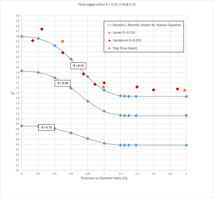
Graphical Comparison of Results:

Commentary:
The published k0 loss coefficients compare well with the calculated results.
Note: Head Loss in m fluid = (k0 * v2) / 2g
- where v = fluid velocity in m/s at the entrance to the orifice, g = acceleration due to gravity in m/s2
- k0 is not the same as a standard k value (which is used in formulas where v = velocity in the pipe)

